
DonCorson
[AHCI]
3358

A David Walter Double Pendulum Clock – Part 9, The Equation Wheel
A David Walter Double Pendulum Clock
– Part 9, The Equation Wheel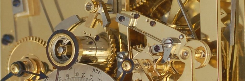
Every week we are seeing more of David's work on his new double pendulum clock.
The equation wheel is one of the more esoteric pieces of the movement. Its purpose it to drive a minute hand that is offset as necessary to show the difference between mean time and solar time. Often the equation of time is only shown with a hand indicating the difference, on this clock there will be two hands, one showing mean time and the other solar time.
For those of you who didn't see the earlier installments of this series, you can catch up by looking here:
- Installment 1 – Introduction and Cutting out the plates
- Installment 2 – Making the Barrel
- Installment 3 – The Suspension
- Installment 4 – Invar Pendulum Parts
- Installment 5 – Making the Wheels
- Installment 6 – Completing the Barrels, Cutting some Pinions
- Installment 7 – The Escape Wheels
- Installment 8 – The Mean/Solar Movement Main Train
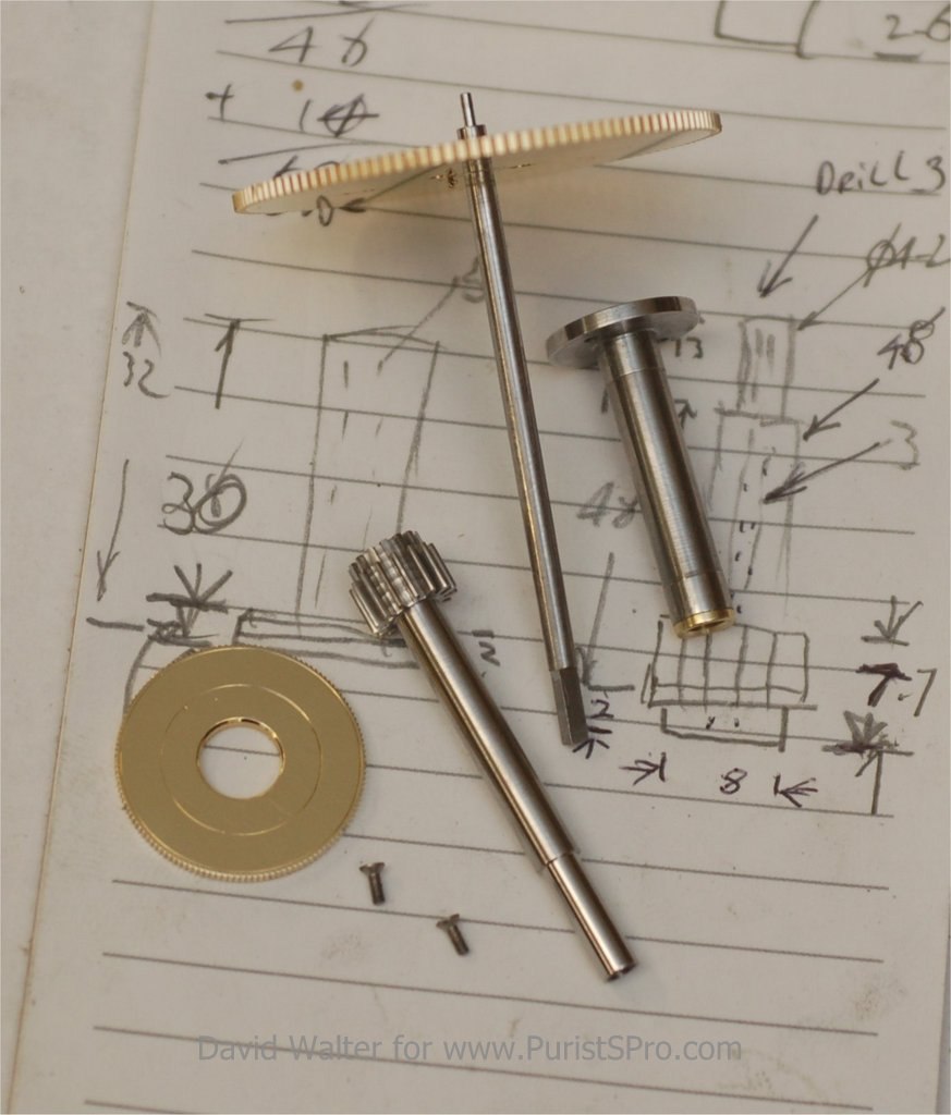
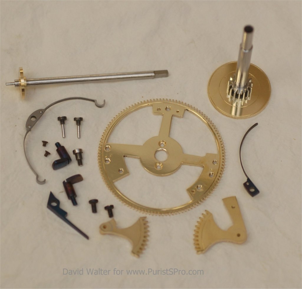
We start out with the equation wheel fitted to the shaft, we see the partially finished pinion, the footed steel tube is fitted to the equation wheel cock. This will become the hour wheel post and the equation pinion upper pivot.
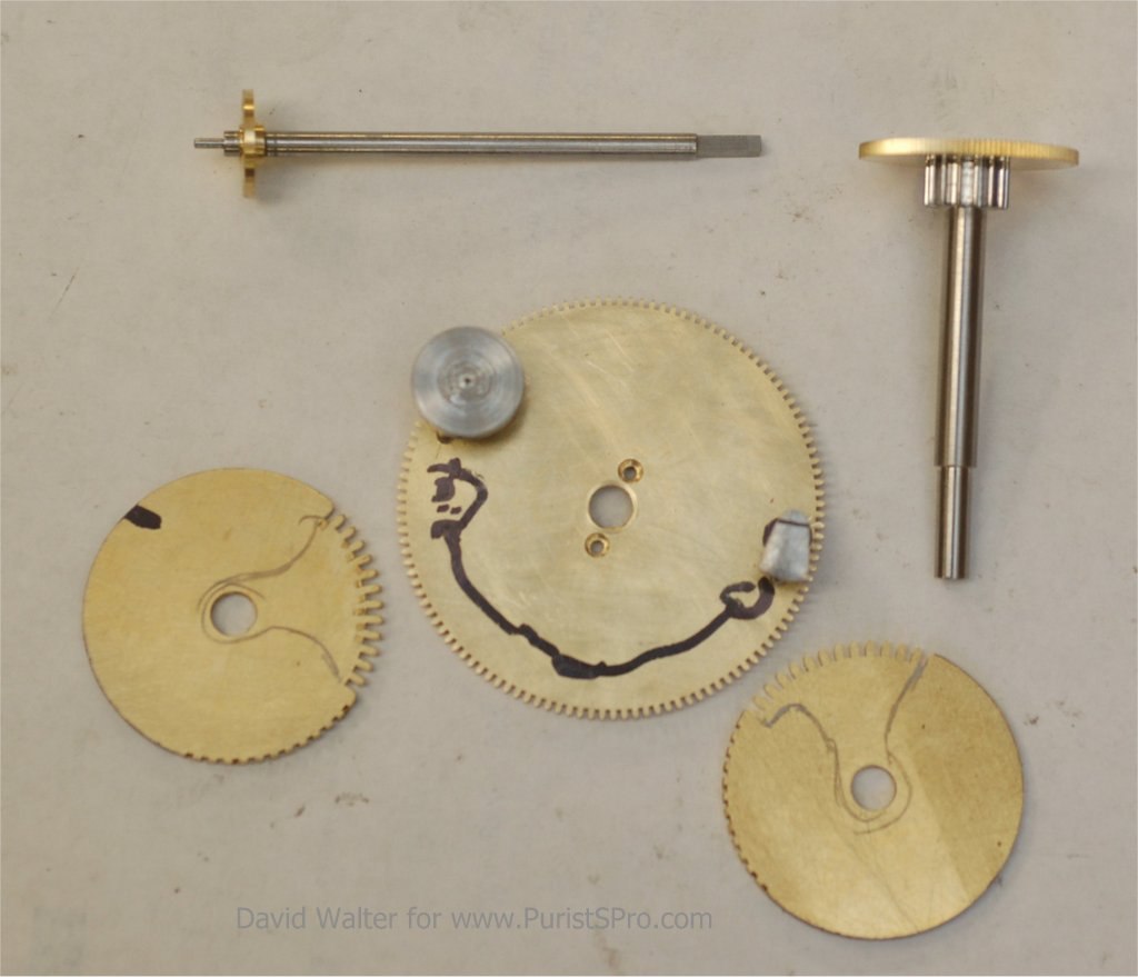
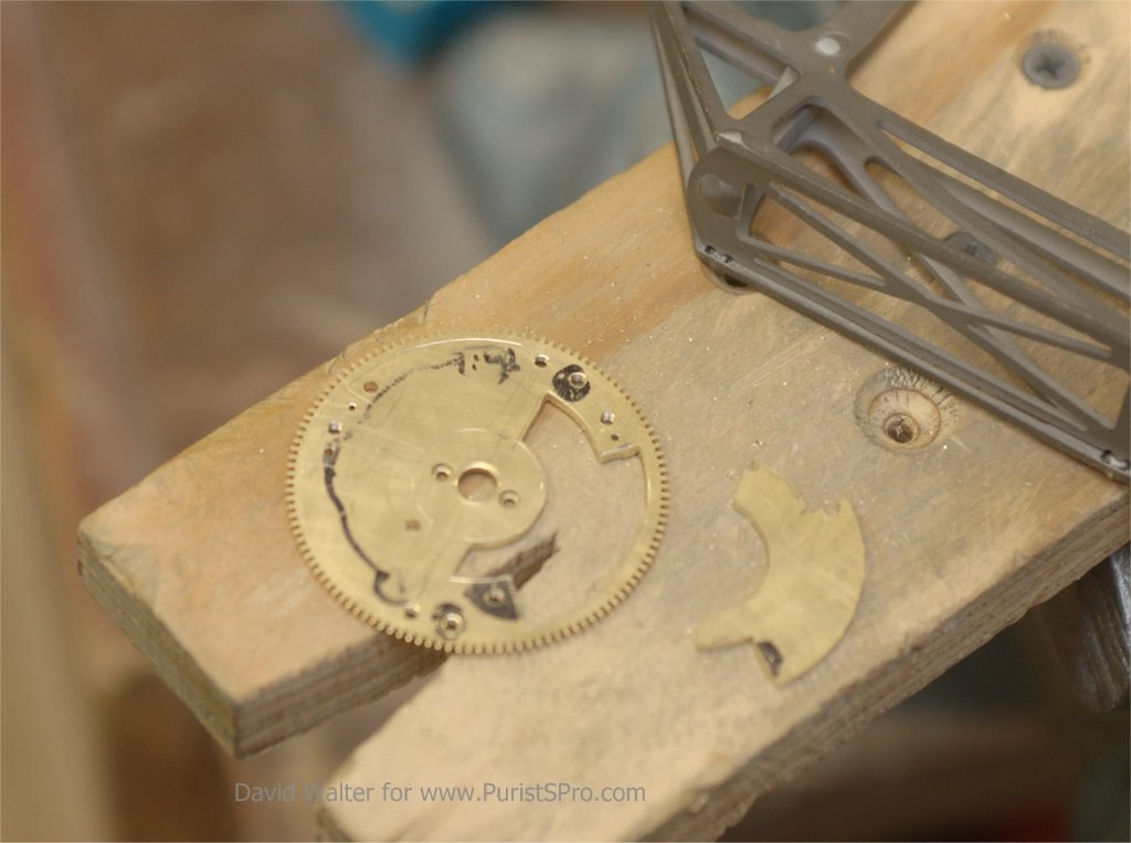
We are now heading into the mechanism that will allow the relative movement of the solar hand coming from a mechanical signal from the equation cam. This is a kind of differential. The movement is transferred to the shaft through two gear portions known as quadrants. The quadrants are pivoted on hardened steel posts and held in place by L-shaped screws known as dogs. Here we see the quadrants with the teeth already cut. The approxmate final form is marked on the material. The dogs will later be filed to shape.
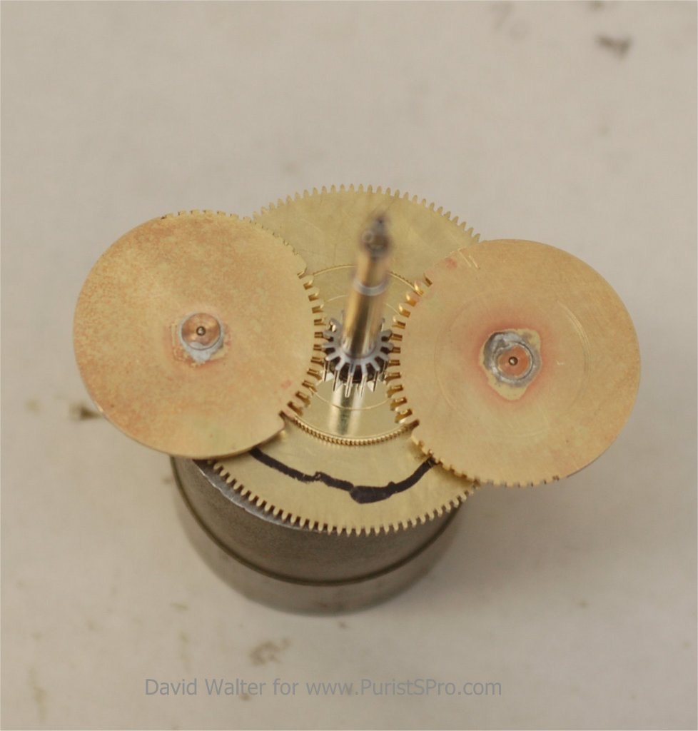
The quadrant wheels in place and meshing with the pinion.
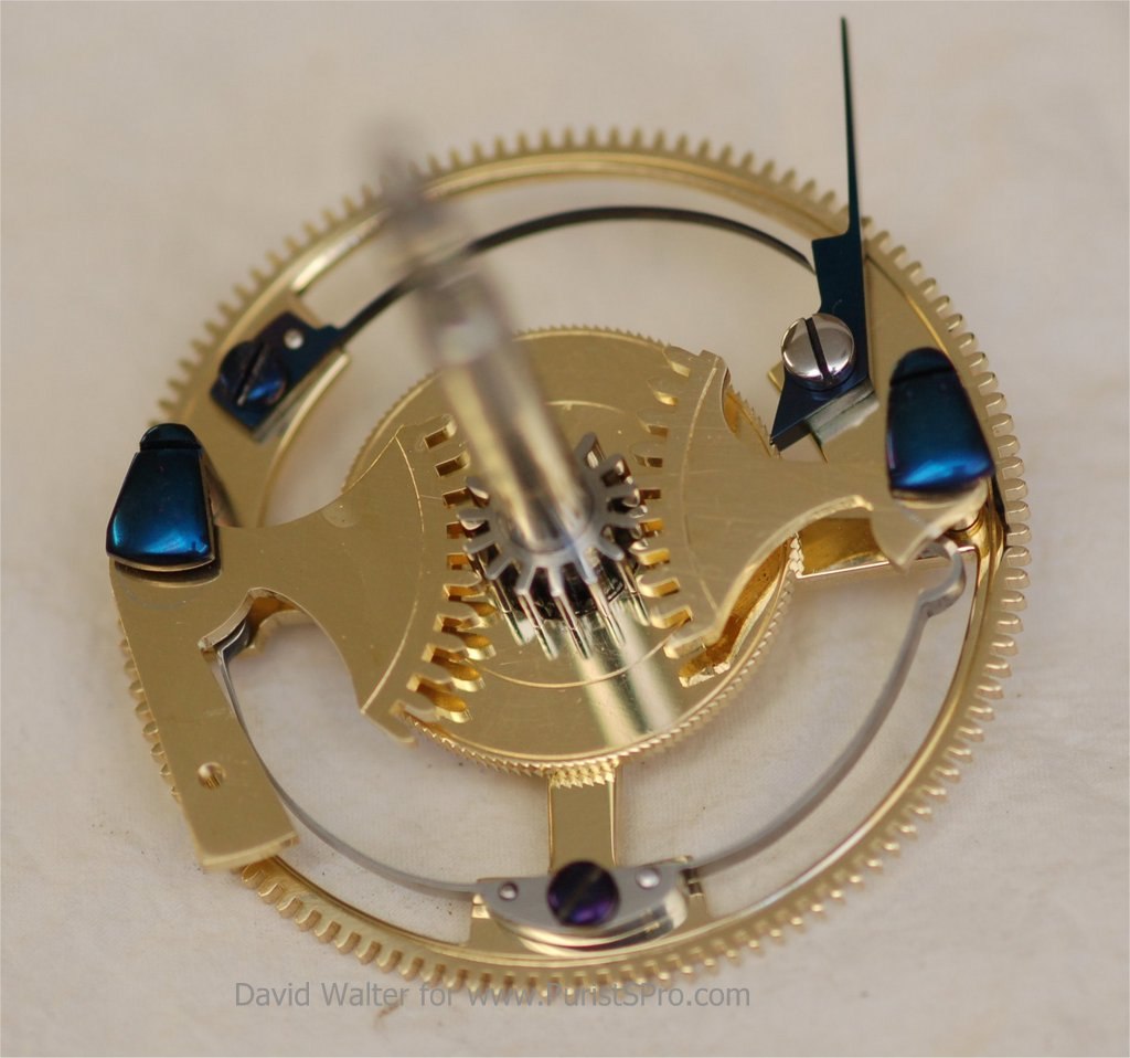
After all the parts have been placed on the wheel the holes are drilled. The non-useful material can then be removed.
The equation wheel components finished, cleaned, polished and ready for assembly.
The assembled equation wheel.
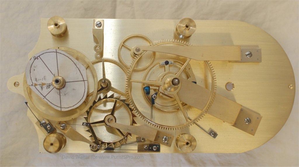
The mechanism fitted to the plate. The 24 hour wheel, equation date change detent, equation year wheel and the year click are all fitted in place. The rough equation cam is resting on its collar ready to be profiled. The lower end of the plates with its scalloped edges have also been brought to shape, the escape wheel will be pivoted in the jewel we see there are the far left of this picture.
The complications are increasing, what is next ?
A David Walter Double Pendulum Clock – Part 9, The Equation Wheel
Setting up the equation wheel

Setting the Equation
Ahh, makes sense