Comments:


Incredible! Grand Seiko T0 Coaxial Remontoire Tourbillon
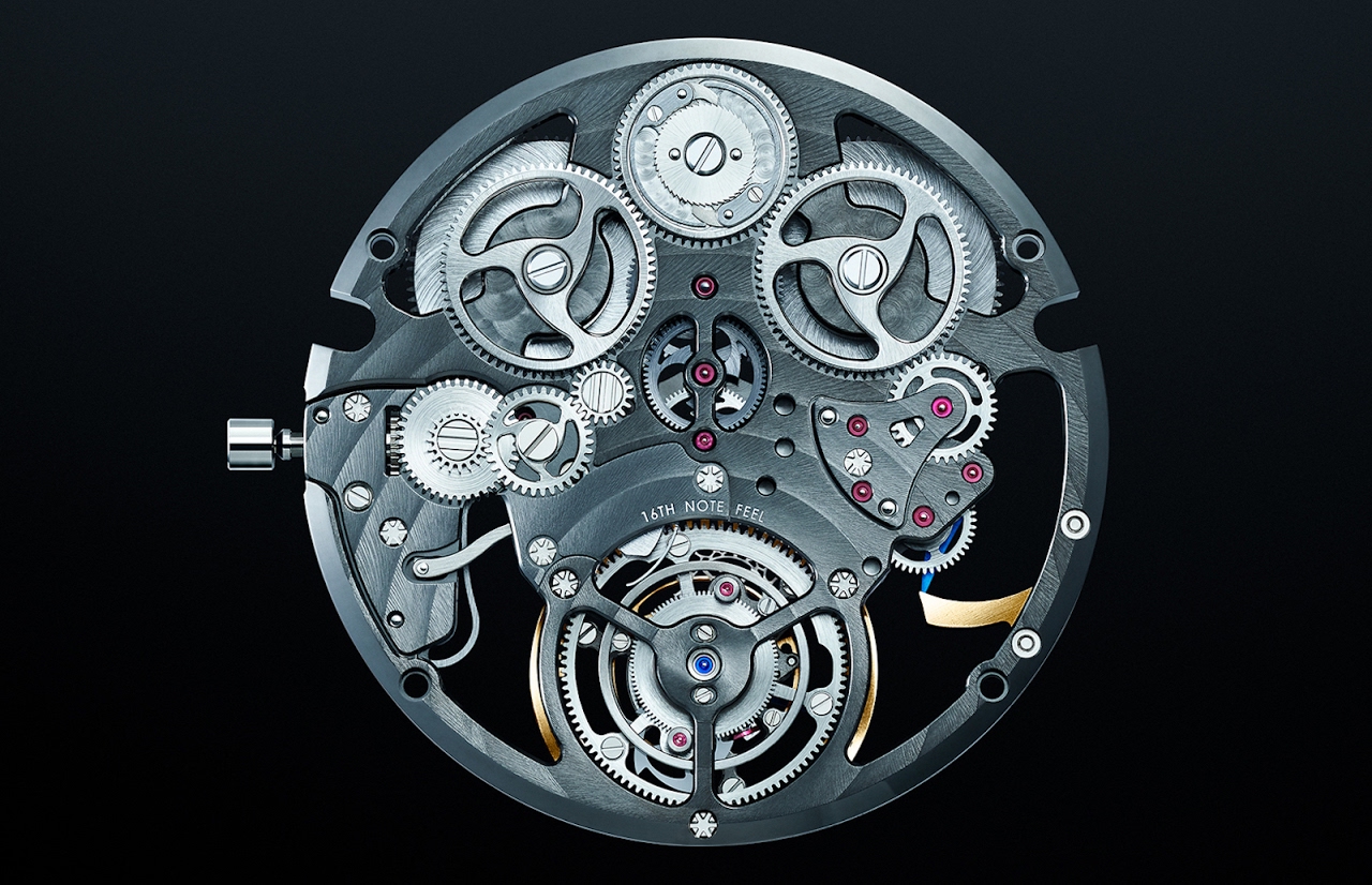
The T0 (T-zero) Constant-force Tourbillon.
Grand Seiko reveals an exciting concept creation with a world’s-first mechanism.
Ever since the first Grand Seiko watch was born in 1960, the pursuit for high accuracy has been fundamental in every Grand Seiko timepiece and innovation. Today, a new and exciting moment in its 60-year history is marked by the introduction of the brand's first-ever concept creation.
The new creation is a masterwork and true revolution in watchmaking design and fully reveals the Grand Seiko designers' capabilities and ingenuity. The T0 (T-zero) Constant-force Tourbillon incorporates a fully integrated constant-force mechanism and tourbillon on the same axis for the first time in the world. The constant-force mechanism provides even energy distribution to the escapement regardless of how much the mainspring is wound, and the tourbillon eliminates the error in precision caused by gravity by incorporating the escapement parts and balance in a rotating carriage. These two mechanisms alone require exceptional design and manufacturing technologies, and the integration of the mechanisms as one unit is a patented design that achieves a new level of accuracy for Grand Seiko's mechanical watchmaking.
In pursuit of the highest level of accuracy for mechanical watchmaking, the designers conceptualized the new creation without restrictions from production capability considerations. The free approach to development resulted in the birth of T0 and inspired essential movement parts for the new Caliber 9SA5, which was developed in parallel with the concept creation.
T0 is displayed on the second-floor lounge of the Grand Seiko Studio Shizukuishi inaugurated on July 20, 2020, in Shizukuishi, Morioka.
The rotating tourbillon and intermittent turning of the constant-force as well as the rhythmical 16th note ticking sound of the mechanisms can be thoroughly enjoyed.
As soon as the Coronavirus situation allows, the new studio looks forward to welcoming visitors.
MORE DETAILS to come -- the patent illustrations and description are in a separate file below. Please explain the two images below -- if you can you are a better man than I!
Cazalea
The Constant Force Tourbillon from Grand Seiko: Swiss Patent CH 708 526 A2, US 905 269 3B2
NOTE: There's a good reason why we don't normally give you the text of patents. They are virtually impenetrable! Also available in French HERE
Inventors Takuma Kawauchiya, Takashi Niwa, Masahiro Nakajima, Masayuki Koda
Description
THE CLAIMS
1. A constant force device for adjusting an output torque, comprising:
- an output unit (34) which produces the output torque by rotating about an output axis;
- a constant force spring (68) which provides a rotational force to the output unit (34);
- an input unit (33) which stores a resilient force in the constant force spring (68) by rotating about an input axis;
- a wheel and lock gear assembly (70; 370; 470) which is rotatably supported about a stop wheel axle body (71) in the input unit (33); and which can turn around the input axis;
- and a stop (96; 196; 496) which rotates about the output axis with the output unit (34) and which engages with the wheel and pinion gear assembly (70; 370; 470); ) responsive to rotation of the wheel and idler gear (70; 370; 470) which rotates about the stop wheel axle body (71).
2. The constant force device of claim 1, wherein the input axis and the output axis are coaxially disposed relative to each other.
3. The constant force device of claim 1 or 2, further comprising: a fixed wheel and pinion assembly (31; 331) which is positioned coaxially with the input axis and which can not rotate with the drive unit (33) and the output unit (34), wherein the wheel and lock gear assembly (70; 370; 470) comprises a stop wheel axle body (71) in which stop wheel axis serves as the axial center, and wherein the stop wheel axle body (71) is configured to be rotatable about the input axis by being positioned to engage taken with the wheel and fixed gear assembly (31; 331).
4. The constant force device according to any one of claims 1 to 3, wherein the wheel and pinion gear assembly (70; 370; 470) has a toothed surface substantially having the shape of an arc wherein input axis serves as a center.
5. Constant force device according to any one of claims 1 to 4, wherein the output unit (34) supports a rocker arm with spring balance (101) so as to be rotatable.
6. The constant force device according to any one of claims 1 to 4, wherein the output unit (34) is configured with respect to one of a wheel and escapement pinion assembly (1 1 1 240), a second wheel and pinion assembly (27; 227), a third wheel and pinion assembly (26) and a central wheel and pinion assembly (25).
7. The constant force device according to any one of claims 1 to 6, further comprising: a phase shift control mechanism (160) which regulates a rotational movement of the output unit (34) relative to the input unit (33), wherein the phase shift control mechanism (160) regulates the rotational movement in a direction in which a phase of the input unit (33) is lagging behind the unit output (34).
8. The constant force device according to claim 7, wherein the phase shift control mechanism (160) regulates the rotational movement in a direction in which a phase of the input unit (33) is in advance with respect to the output unit (34).
9. The constant force device of claim 7 or 8, wherein the phase shift control mechanism (160) comprises: a protrusion which is formed in one of the output and input units (33; 34); and a hole which is formed in the other unit among the output unit (34) and input unit (33), and which is engageable with the protrusion.
10. A movement comprising: a constant force device (3) according to claim 1; and a pendulum beam (101) which is actuated by an output torque provided by the constant force device.
11. A mechanical watch comprising: the movement of claim 10. 23
BACKGROUND OF THE INVENTION
1. Field of the invention
The present invention relates to a constant force device, a movement and a mechanical watch.
2. Description of the Related Art
In a mechanical watch, if a torque transmitted to a wheel assembly and escapement pinion of an escapement from a barrel drum varies in response to the unwinding of a mainspring of the barrel drum, an oscillation angle that forms a pendulum with a balance spring changes and the rate of a watch changes. Therefore, to suppress the variation of the rotational torque transmitted to the wheel and escapement pinion assembly, a constant force device is proposed in which a constant force spring (pre-tension spiral spring) is disposed between the drum. barrel and escapement.
For example, as a constant force device, there are provided devices which comprise a wheel and stop gear assembly with a stop gear (stop wheel gear), a wheel and pinion gear assembly. escapement with an escapement pinion (escapement escapement wheel shaft), a hose clamp mounted on a clamping pinion, a constant-force spring provided between the clamping collar and the wheel and pinion assembly escapement and a cam mounted on the escapement pinion. The constant force spring applies a rotational force to the wheel and escapement pinion assembly so that the wheel and escapement pinion assembly rotates relative to the clamp (see, for example, Japanese Patent No. 4,105,941 (Patent Reference 1)).
According to this configuration, when the rotation of the wheel and escapement pinion assembly is stopped or restarted by a pallet of a first anchoring device, the rotation of the wheel and pinion stop assembly is stopped. or restarted by a pallet of a second anchoring device. The second anchor is caused to perform oscillation movement by a fork-shaped portion that engages the cam. Then, if the rotation of the wheel and lock gear assembly is restarted, the clamping collar rotates. In this way, the constant force spring is wound in a regular manner. Therefore, it is possible to suppress the variation of the rotational torque transmitted to the wheel and escapement pinion assembly.
Incidentally, in the related art described above, the rotation of the wheel and stop gear assembly is stopped or restarted by causing the second anchor device to perform an oscillation movement using cam and fork-shaped portion. There is therefore a problem of increasing energy loss for stopping or restarting the rotation of the wheel and pinion assembly.
SUMMARY OF THE INVENTION
One aspect of the present application is to provide a constant force device, a movement and a mechanical watch which can reduce a loss of energy to control the rotation of a wheel and pinion assembly.
It is proposed a constant force device for adjusting the output torque according to the present application. The constant force device comprises an output unit which produces the output torque by rotating about an output axis, a constant force spring which applies a rotational force to the output unit, an input unit which stores a resilient force in the constant force spring by rotating about an input axis, a wheel and pinion assembly which is rotatably supported (revolution about its axis) around a body of stop wheel axle in the input unit, which is rotatable (rotation about it) about the input axis, and a stop which rotates about the output axis at the same time as the output unit and which engages with the wheel and pinion gear assembly in response to the rotation of the wheel and pinion gear assembly which rotates about the wheel axle body stop.
In this way, it is possible to stop or restart the rotation of the wheel assembly and pinion stop and adjust a degree of progression of its rotation by rotating the stop around the axis of exit. Therefore, a movement of the uncoupled abutment of the wheel and idler assembly functions as the rotational movement similar to the wheel and idle gear assembly, thereby reducing the energy loss. In other words, since a transmission path is simplified between the wheel and pinion gear assembly and the output unit, it is possible to decrease the loss experienced by the output unit from the wheel and pinion assembly. It is therefore possible to more stably guarantee the output torque of the output unit.
In the constant-force device according to the present application, the input axis and the output axis are arranged coaxially with respect to one another.
According to this configuration, since a transmission distance is effectively shortened between the wheel and pinion gear assembly and the output unit, it is possible to further remove the loss.
The constant force device according to the present application further comprises a wheel and fixed gear assembly which is arranged coaxially with the input shaft and which can not rotate with the input unit and the unit of exit, in others
2 terms a fixed wheel and pinion assembly which is arranged to be separated from the rotational movement of the input unit and the output unit by itself. The wheel and pinion assembly has a stop wheel axle body in which the stop wheel axle serves as an axial center, the stop wheel axle body configured to be rotatable around the input shaft being arranged to engage the wheel and fixed gear assembly.
According to this configuration, the wheel and pinion assembly can achieve a planetary movement for revolution and rotation, while meshing with the wheel and fixed gear assembly. Therefore, the wheel and pinion assembly can execute revolution and rotation by rotating about the input axis of the input unit to which the wheel and pinion assembly is attached. way to turn. It follows that it becomes possible to adjust the degree of progression of the rotation of the wheel and pinion assembly using a simple structure. Therefore, it is possible to effectively use a space around the input unit and the wheel and pinion assembly. Then, in conjunction with an effective spatial arrangement for the abutment described above, the constant force device can be effectively installed.
In the constant force device according to the present application, the wheel and pinion gear assembly has a toothed surface having substantially the shape of an arc in which the input axis serves as a center.
As described above, the wheel and pinion gear assembly has the arcuate toothed surface in order to obtain a friction angle, that is to say the toothed surface having essentially the shape of an arc, in which the input axis serves as a center. Therefore, the tooth surface of the teeth of the wheel and pinion gear assembly is formed in accordance with a locus of movement of the abutment. Therefore, when the wheel and pinion assembly and the stop are engaged with each other, a loss due to friction caused by sliding between these two elements is suppressed and it is possible to prevent the stop to receive an unnecessary load. Therefore, it is possible to suppress the loss of the output unit from the wheel and pinion gear assembly, allowing stable output.
In the constant force device according to the present application, the output unit supports a rocker arm with spring balance so as to be rotatable.
According to this configuration, it is possible to rotate the balance with spring balance at the same time as the output unit. It is therefore possible to reduce the influence of gravity which is caused by an orientation of the balance with pendulum spring. That is, this configuration can function as a vortex mechanism that can suppress a change in pendulum swing cycles with spring balance that is caused by a sense of gravity.
In the constant-force device according to the present application, the output unit is configured relative to one of a wheel assembly and escapement pinion, a second wheel and pinion assembly, a third wheel assembly and pinion and a wheel and central gear assembly.
According to this configuration, it is possible to save the placement space of the device with constant force. A component configuring the constant force device may be shared with a component configuring an escapement or a train wheel. Therefore, it is possible to reduce the number of components in the constant force device.
The constant-force device according to the present application further comprises a phase shift control mechanism which regulates a rotational movement of the output unit relative to the input unit. The phase shift control mechanism regulates at least the rotational movement in a direction in which a phase of the input unit is delayed relative to the output unit.
According to this configuration, it is possible to prevent the phase of the input unit from being delayed with respect to the output unit. Therefore, for example, when a second hand or the like is placed in the input unit, it is possible to prevent a strongly offset display of the second hand.
In addition, it is possible to regulate the maximum separation distance between the wheel assembly and stop pinion and the abutment. Therefore, for example, including when a sudden input torque is applied to the input unit and the wheel and pinion gear assembly suddenly collides with the stopper, it is possible to reduce the collision force. Therefore, it is possible to prevent damage to the stopper or wheel and pinion assembly.
In the constant force device according to the present application, the phase shift control mechanism regulates the rotational movement in a direction in which a phase of the input unit is in advance with respect to the output unit. .
According to this configuration, when the output unit rotates in the opposite direction due to an impact due to a fall or the like, it is possible to prevent the wheel and pinion stop assembly and the stop be damaged due to collision of the stop with the wheel and pinion assembly.
In the constant-force device according to the present application, the phase shift control mechanism has a protuberance which is formed on one of the output and input units, and a hole which is formed in the other unit. among the output unit and the input unit, and which can engage with the protrusion.
According to this configuration, it is possible to allow the phase shift control mechanism to have a simple structure.
[0026] A movement according to the present application comprises the constant force device and a pendulum beam which is set in motion by an output torque provided by the constant force device.
According to this configuration, it is possible to provide the movement which can reduce the energy loss to limit the rotation of the wheel and pinion assembly.
A mechanical watch according to the present invention comprises the movement.
According to this configuration, it is possible to provide the mechanical watch which can reduce the energy loss to limit the rotation of the wheel assembly and pinion stop.
According to the present application, it is possible to stop or restart the rotation of the wheel assembly and pinion stop and adjust the degree of progression of its rotation by rotating the stop around the axis Release. As a result, the movement of the uncoupled abutment of the wheel and idler assembly functions as the rotational movement similar to the wheel and idler assembly, thereby reducing the energy loss. In other words, since the transmission path is simplified between the wheel and sprocket assembly and the output unit, it is possible to decrease the loss experienced by the output unit from the set. wheel and pinion. It is therefore possible to more stably guarantee the output torque of the output unit.
BRIEF DESCRIPTION OF THE SKETCHES [0031]
Fig. 1 is a plan view of a front side of a movement of a mechanical watch according to a first embodiment of the present invention.
Fig. 2 is a perspective view of a vortex with a constant force device according to the first embodiment of the present invention.
Fig. 3 is a cross-sectional view taken along the axis A-A of FIG. 2.
Fig. 4 is a perspective view when an outer carriage according to the first embodiment of the present invention is seen from a fixed wheel bridge side.
Fig. 5 is a perspective view when the outer carriage according to the first embodiment of the present invention is seen from a carriage bridge side.
Fig. 6 is a plan view of a stopping wheel according to the first embodiment of the present invention.
Fig. 7 is a perspective view when an inner carriage according to the first embodiment of the present invention is seen from a fixed wheel bridge side.
Fig. 8 is a perspective view when the inner carriage according to the first embodiment of the present invention is seen from a carriage bridge side.
Fig. 9 is a perspective view of a bearing unit of an escapement mechanism according to the first embodiment of the present invention.
Fig. 10 is a plan view of the escapement mechanism according to the first embodiment of the present invention.
Fig. 11 is a view illustrating an operation of a wheel and idler assembly, an abutment 96, and a wheel and idler assembly according to the first embodiment of the present invention, FIGS. 11 to 11d are illustrating a gradual change.
Fig. 12 is a perspective view when a main portion according to a first modification example of the first embodiment of the present invention is viewed from a fixed wheel bridge side.
Fig. 13 is a perspective view of a stopper according to the first modification example of the first embodiment of the present invention.
Fig. 14 is a perspective view when a main portion according to a second modification example of the first embodiment of the present invention is viewed from a fixed wheel bridge side.
Fig. 15 is a perspective view of an eccentric pin according to the second modification example of the first embodiment of the present invention.
Fig. 16 is a plan view of a phase shift control mechanism according to the second modification example of the first embodiment of the present invention.
FIG. 17 is a partially enlarged plan view illustrating a coupling state between a stop wheel and a stop according to a third exemplary modification of the first embodiment of the present invention.
Fig. 18 is a plan view illustrating a coupling state between a stop wheel and a pawl of an abutment according to a fourth modification example of the first embodiment of the present invention.
Fig. 19 is a plan view of a stopping wheel according to a fifth exemplary modification of the first embodiment of the present invention.
Fig. 20 is a plan view of a constant force device according to a second embodiment of the present invention.
Fig. 21 is a cross-sectional view taken along the axis B-B of FIG. 17.
Fig. 22 is a cross-sectional view of a constant force device according to an exemplary modification of the second embodiment of the present invention.
DETAILED DESCRIPTION OF THE PREFERRED EMBODIMENTS (First Embodiment a Mechanical watch)
In the following, a first embodiment of this invention will be described with reference to FIGS. 1 to 11. [0033] FIG. 1 is a plan view of a front side of a movement of a mechanical watch 1.
As shown in the figure, the mechanical watch 1 is configured to have a movement 10 and a housing (not shown) which accommodates the movement 10.
The movement 10 has a main plate 11 configuring a frame. A dial (not shown) is placed at the rear of the main stage 11. A train wheel integrated at the front of the movement 10 is called a front wheel and a train wheel integrated at the rear of the movement. 10 is called a rear wheel.
A winding stem guide hole 11a is formed in the main plate 11 and a winding rod 12 is integrated so as to rotate. The winding stem 12 has a position axially determined by a switching device provided with an adjusting lever 13, a player 14, a sliding spring 15 and a setting lever jumper 16. , a winding pinion 17 is provided so as to be able to rotate on a guide axis of the winding stem 12.
In such a configuration, if the winding stem 12 is turned into a state in which the winding stem 12 is placed in a first winding stem position (step zero), which is the closest to the inside of the movement 10 in a direction of axis, the winding pinion 17 rotates via the rotation of a clutch wheel (not shown). Then, if the winding pinion 17 rotates, a meeting wheel 20 meshing with it rotates. Then, if the encounter wheel 20 turns, a ratchet 21 meshing with it turns. In addition, if the ratchet 21 rotates, a main spring (not shown) housed in a barrel wheel 22 is wound.
The front wheel of the movement 10 is configured to include not only the barrel wheel 22, but also a wheel and central gear assembly 25, a third wheel and pinion assembly 26, a second wheel and pinion assembly 27 and a fifth assembly wheel and pinion 28, and exerts a function of transmitting a rotational force of the barrel wheel 22. In addition, a vortex with constant force device 30 which limits the rotation of the front wheel is placed at the front of the movement 10.
The wheel and central gear assembly 25 meshes with the barrel wheel 22. The third wheel and pinion assembly 26 meshes with the wheel assembly and central gear 25. The second wheel and pinion assembly 27 's meshes with the third wheel and pinion assembly 26. The fifth wheel and pinion assembly 28 meshes with the second wheel and pinion assembly 27. Then, the constant force vortex 30 meshes with the fifth wheel and pinion assembly 28 .
(Tourbillon with constant force device)
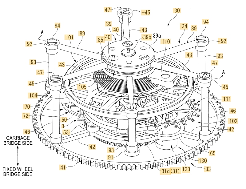
FIG. 2 is a perspective view of the vortex with constant force device 30, FIG. 3 being a cross-sectional view taken along the axis A-A of FIG. 2.
As shown in Figs. 2 and 3, the vortex with constant force device 30 is a mechanism for limiting the rotation of the front wheel described above. In addition, the vortex with constant force device 30 has what is called a vortex mechanism which reduces the influence of gravity which is caused by an orientation of a pendulum with pendulum spring 101 (which will be described later) and eliminates a disordered operation of the balance with pendulum spring 101. In addition, the vortex with constant force device 30 comprises a device with constant force which removes the variations in the torque transmitted to a wheel assembly and pinion 111 escapement (which will be described later).
In the following, the vortex with constant force device 30 will be described in detail.
The vortex with constant force device 30 comprises a fixed wheel and gear assembly 31 which is fixed to the main platinum side 1 1 in a fixed wheel bridge 29 attached to the front of the main plate 1 1, an outer carriage (Input unit) 33 which is attached to the rear of the main plate 1 1 and which is rotatably supported between the fixed wheel bridge 29 (see Fig. 3) and a carriage bridge 32 placed at the opposite of the fixed wheel bridge 29, and an inner carriage (output unit) 34 which is supported inside the outer carriage 33 so as to be rotatable relative to the outer carriage 33.
The wheel and fixed gear assembly 31 has a wheel main body 31a having substantially the shape of a disk. A hole stone 31b which supports the outer carriage 33 in a rotatable manner is located in a substantial center of the wheel main body 31a in a radial direction. In addition, a screw insertion hole 31c which attaches and fixes the fixed wheel and pinion gear 31 to the fixed wheel bridge 29 is formed in the periphery of the hole stone 31b of the wheel main body 31a. A screw (not shown) is inserted into the screw insertion hole 31c. In addition, a toothed portion 31d is formed on an outer peripheral portion of the wheel main body 31a.
FIG. 4 is a perspective view of the outer carriage 33 seen from the fixed wheel bridge side 29.
FIG. 5 being a perspective view of the outer carriage 33 seen from the carriage bridge side 32.
As shown in FIGS. 2 to 5, the outer carriage 33 has a first substantially disk-shaped outer carriage bearing 35 disposed on the fixed wheel bridge side 29 and a second substantially disk-shaped outer carriage bearing 36 disposed on the carriage bridge side 32. The first outer carriage bearing 35 and the second outer carriage bearing 36 are arranged coaxially with the wheel and fixed gear assembly 31.
In addition, a hole stone 35a is disposed coaxially with the hole stone 31b of the fixed wheel and pinion assembly 31 in the first outer carriage bearing 35. The hole stone 35a is used to support a carriage interior 34 so that it can rotate. In addition, a first outer rotating body 37 is provided on the fixed wheel bridge surface 29 of the first outer carriage bearing 35.
In order to correspond to a shape of the first outer carriage bearing 35, the first outer rotary body 37 is configured to integrally mold a base 37a having substantially the shape of a disk and a pin 37b which protrudes to the side fixed wheel bridge 29 from an essential center of the base 37a in the radial direction. The base 37a is attached and fixed to the first outer carriage bearing 35 via a screw 38. In addition, the post 37b is inserted into the hole stone 31b of the wheel and fixed gear assembly 31. In this way, the first outer rotary body 37 is rotatably supported via the wheel and fixed gear assembly 31.
In contrast, a hole stone 36a is arranged coaxially with the hole stone 35a of the first outer carriage bearing 35, in the second outer carriage bearing 36. The hole stone 36a is also used to support the inner carriage. 34 in such a way that it can rotate in cooperation with the hole stone 35a of the first outer carriage bearing 35. In addition, a second outer rotary body 39 is provided on the carriage deck side surface 32 of the second carriage bearing. outside 36.
In order to correspond to a shape of the second outer carriage bearing 36, the second outer rotary body 39 is configured to integrally mold a base 39a having substantially the shape of a disk and a pin 39b which protrudes towards the side trolley bridge 32 from an essential center of the base 39a in the radial direction. Post 39b is rotatably supported via a hole 32a of the carriage bridge 32. In addition, the base 39a is attached and secured to the second outer carriage bearing 36 via a screw 40.
In addition, a ring-shaped outer gear 41 is placed on a radially outer side further away from the first outer carriage bearing 35. The outer gear 41 meshes with the fifth wheel and pinion assembly 28. .
In addition, the outer gear 41 and the first outer carriage bearing 35 are connected to one another by three first arms 42. The first three arms 42 extend in the radial direction and are placed at equal intervals in the circumferential direction.
On the other hand, three radially outwardly extending second arms 43 are integrally molded in the outer peripheral portion of the second outer carriage bearing 36. These second arms 43 are placed at equal intervals in the circumferential direction in such a manner that to correspond to the first arms 42 on the side of the first outer carriage bearing 35.
[0054] Disc-shaped shaft washers 44 and 45 are respectively and integrally molded in a connecting portion between the first arm 42 and the external gear 41 and a distal end of the second arm 43. Then, shafts 46 extending axially are respectively placed between the shaft washers 44 and 45. The two ends of the shaft 46 are attached and fixed to the shaft washers 44 and 45 by a screw 47 threaded from the top of the shaft washers 44 and 45.
In addition, a ring-shaped support bridge 48 which surrounds the periphery of the first outer carriage bearing 35 is placed between the first outer carriage bearing 35 and the outer gear 41. The inner diameter of the support bridge 48 is set to be substantially the same as the outer diameter of the toothed portion 31d of the wheel and fixed gear assembly 31.
In addition, the support bridge 48 is integrally molded so as to be connected to the first arm 42. A stop wheel bearing unit 50 and a wheel and stop gear assembly 70 rotatably supported. by the stop wheel bearing unit 50 are placed in the support bridge 48.
Here, the stop wheel bearing unit 50 and the wheel and stop gear assembly 70 configure the constant-force device 3. The constant-force device 3 has a constant-force spring 68 (which will be described later) and a stop 96 in addition to the stop wheel bearing unit 50 and the wheel and pinion gear assembly 70.
The stop wheel bearing unit 50 is configured to have an insertion portion of the ring-shaped shaft body 51 integrally molded onto the support bridge 48, a first wheel bearing. stop 52 mounted on the fixed wheel bridge side 29 of the support bridge 48 and a second stop wheel bearing 53 mounted on the trolley bridge side 32 of the support bridge 48.
The first stop wheel bearing 52 has a wall 54 extending towards the fixed wheel bridge side 29 from a position corresponding to the insertion portion of the axle body 51 of the support bridge 48. wall 54 is formed in a substantially G-shaped sectional sectional configuration so as to open radially on the inside. A substantially disc-shaped bearing washer 55 is integrally molded on an inner peripheral surface of the distal end of the wall 54 so as to be perpendicular to the wall 54. Next, a hole 55a is formed, in the direction of the thickness, in the substantial center of the bearing washer 55 in the radial direction. A hole stone 56 which supports the wheel and pinion assembly 70 so that it can rotate is placed in the hole 55a.
In addition, a pair of posts 57 extending from both sides to the wall 54 are integrally molded on the proximal end side of the wall 54. Disc-shaped screw washers 57a are respectively integrally molded in the distal end of the pair of posts 57. The screw washer 57a is attached and fixed to the support bridge 48 by a screw 58.
In contrast, the second stop wheel bearing 53 has a substantially disc-shaped bearing washer 61 positioned in a position corresponding to the insertion portion of the axle body 51 formed in the support bridge 48. Then, a hole 61a is formed, in the direction of the thickness, in the substantial center of the bearing washer 61 in the radial direction. A hole stone 62 which supports the wheel and pinion assembly 70 so that it can rotate is placed in the hole 61a.
A pair of uprights 63 are integrally molded on both sides in the outer peripheral portion of the bearing washer 61 above the hole stone 62. Disc-shaped screw washers 63a are respectively integrally molded in the distal end of the pair of posts 63. The screw washer 63a is attached and fixed to the support bridge 48 by a screw 64.
Ascending portions 63b are respectively formed in the distal end portion of the screw washer 63a and in the post 63. An interstice S1 is formed between the bearing washer 61, the post 63 and the support bridge 48. A stop wheel 72 configuring the wheel and pinion assembly 70 is placed in the gap S1.
In addition to the stop wheel 72, the wheel and stop gear assembly 70 has a stop wheel axle body 71 inserted in the insertion portion of the axle body 51 formed in the bridge. 48. Studs 71a and 71b are respectively and integrally molded at both ends of the stop wheel axle body 71. The pin 71a of the fixed wheel bridge side 29 is rotatably supported. via the hole stone 56 of the first stop wheel bearing 52. On the other hand, the pin 71b of the carriage bridge side 32 is rotatably supported via the hole 62 of the second wheel bearing. stop 53.
In addition, a stop pinion 71c is integrally molded in the stop wheel axle body 71, from the substantial center axially through the front of the bridge side pin 71a. Here, the inside diameter of the support bridge 48 in which the stop wheel bearing unit 50 is placed is set to be substantially the same as the outside diameter of the toothed portion 31 d of the wheel and fixed gear assembly 31. Consequently, the stop gear 71c is adapted to engage with the toothed portion 31d. In contrast, the stop wheel 72 is externally attached and secured adjacent a base portion of pin 71b of the carriage bridge side 32 in the stop wheel pin body 71. The pin body stop wheel 71 and stop wheel 72 are integrated with each other so as not to be rotatable relative to each other.
FIG. 6 is a plan view of the stop wheel 72.
As illustrated by the figure, for example, the stop wheel 72 is made of a material having a crystal orientation such as a metal material and a single crystal silicon, and is formed by a process called lithography galvanoformung abformung (LIGA ) in which an optical process such as electroforming and photolithography technology is integrated, a deep reactive ion etching (DRIE) or a metal injection molding (MIM).
[0068] The stop wheel 72 is formed by integrally molding a central portion 73 placed and fixed externally on the stop wheel axle body 71, a rim 74 disposed on the outer side in the radial direction of the central portion 73 and having the shape of a ring so as to surround the periphery of the central portion 73, and a radius 75 connecting the central portion 73 and the flange 74.
Multiple hooks 76 (five in this embodiment) are formed to protrude radially outward in the outer peripheral portion of the flange 74. More specifically, the hook 76 is formed in a substantially triangular shape such as the shows the plan view in the axial direction, a substantially triangular opening 76a being formed in a most central portion thereof. In addition, the hook 76 is formed so that a vertex P1 thereof is oriented in a direction of rotation (clockwise in Fig. 6) Y1 of the wheel. 72. A side side 76b of the front side in the direction of rotation Y1 is set to be shorter than a side side 76c of the rear side in the direction of rotation Y1. In other words, while the lateral side 76b of the front side is formed to be connected to the spoke 75, the side side 76c of the back side is formed to be connected to the flange 74. The details of a rotation operation of the Stopwheel 72 will be described later.
Here, the radius 75 and the lateral side 76b of the front side have the shape of an arc. Then, the center of the arc is located coaxially with an axial center C1 of the wheel assembly and fixed gear 31, that is to say the center of rotation of the outer carriage 33.
According to this configuration, the stop 96 (which will be described later) placed in the inner carriage 34 is engaged with the lateral side 76b of the front side of the hook 76 or uncoupled thereof.
In addition, as shown in FIGS. 4 and 5, in the support bridge 48, a ring-shaped bearing unit insertion portion 65 is integrally molded on one side which is diametrically opposed to the insertion portion of the axis body 51 in the first outer carriage bearing 35. A bearing 133 of an escapement mechanism bearing unit 130 (to be described later) is inserted into the bearing unit insertion portion 65. one of the first three arms 42 protrudes from the outer peripheral portion of the bearing unit insertion portion 65.
In addition, a bolt carrier 66 is integrally molded in a position adjacent to the bearing unit insertion portion 65 in the support bridge 48. A bolt 67 is mounted to fit tightly in the bolt carrier. 66. An outer end portion of the constant force spring 68 is attached to the stud holder 66.
The constant force spring 68 serves to apply a rotational force to the inner carriage 34 relative to the outer carriage 33 and is formed in a spiral shape. An inner end portion of the constant force spring 68 is attached to the inner carriage 34 via a ferrule 69.
(Inside trolley)
FIG. 7 is a perspective view of the inner carriage 34 as seen from the fixed wheel bridge side 29, FIG. 8 being a perspective view of the inner carriage 34 as seen from the carriage bridge side 32.
As shown in FIGS. 2, 3, 7 and 8, the inner carriage 34 has a first substantially disk-shaped inner carriage bearing 81 disposed on the fixed wheel bridge side 29 and a second substantially disk-shaped inner carriage bearing 82 disposed on the bridge side. The first inner carriage bearing 81 and the second inner carriage bearing 82 are arranged coaxially with the first outer carriage bearing 35 and the second outer carriage bearing 36 of the outer carriage 33.
In addition, a first inner rotational body 83 is provided on the surface of the first inner carriage bearing 81 on the first outer carriage bearing side 35. In order to correspond to a shape of the first inner carriage bearing 81, the first body inner rotator 83 is formed by integrally molding a base 83a which is substantially disk-shaped, an axle 83b protruding toward the first outer carriage bearing side 35 from the substantial center of the base 83a in the radial direction, and a pin 83c protruding from the distal end of the axis 83b.
Then, the base 83a is attached and fixed to the first inner carriage bearing 81 via a screw 84. In addition, the post 83c is inserted into the hole stone 35a of the first outer carriage bearing 35. In this way, the inner carriage 34 is rotatably supported relative to the outer carriage 33.
In addition, the constant force spring 68 and the ferrule 69 are fixed to the axis 83b. In this manner, a biasing force of the constant-force spring 68 is applied to the inner carriage 34 relative to the outer carriage 33. That is, a rotational force is applied to the inner carriage 34 relative to the carriage external 33 by the spring with constant force 68.
In contrast, a second inner rotatable body 85 is provided on the surface of the second inner carriage bearing 82 on the second outer carriage bearing side 36. In order to correspond to a shape of the second inner carriage bearing 82, the second body Inner rotary gear 85 is formed by integrally molding a base 85a having substantially the shape of a disc and a pin 85b which protrudes towards the second outer carriage bearing side 36 from the substantial center of the base 85a in the radial direction. The post 85b is rotatably supported via the hole stone 36a of the second outer carriage bearing 36. In addition, the base 85a is attached and secured to the inner carriage second bearing 82 via a screw 86.
In addition, anti-blocking bearings 87a and 87b are respectively placed in the first inner carriage bearing 81 and the second inner carriage bearing 82. The anti-blocking bearings 87a and 87b are disposed coaxially with respect to the hole stone 35a. the first outer carriage bearing 35 and the hole stone 36a of the second outer carriage bearing 36. The anti-blocking bearings 87a and 87b serve to support the rocker spring balance 101 (to be described later) so that he can turn.
Three radially outwardly extending first arms 88 are integrally molded into the outer peripheral portion of the first inner carriage bearing 81. In addition, three radially outwardly extending second arms 89 are integrally molded into the outer peripheral portion of the second inner carriage bearing 82. The first arms 88 and second arms 89 are respectively placed at equal intervals in the circumferential direction; in addition, they are arranged so as to face each other in the axial direction. In addition, the respective first arms 88 are arranged to be located between the first three arms 42 which are respectively formed in the outer carriage 33. In addition, the respective second arms 89 are arranged to be located between the three second arms 43 which are respectively formed in the outer carriage 33.
In addition, substantially disc-shaped shaft washers 91 and 92 are respectively integrally molded into the distal end of the respective arms 88 and 89. Then axially extending shafts 93 are respectively placed between the shaft washers 91 and 92. Both ends of the shaft 93 are attached and secured to the shaft washers 91 and 92 by a screw 94 threaded from the top of the shaft washers 91 and 92.
In addition, a support bridge 95 having the shape of a ring so as to surround the periphery of the first inner carriage bearing 81 is placed outside the first inner carriage bearing 81 in the radial direction. The inside diameter of the support bridge 95 is set to be substantially the same as the outside diameter of the toothed portion 31 d of the wheel and fixed gear assembly 31. In addition, the support bridge 95 is integrally molded so as to be connected to the first arm 88.
The stop 96 is disposed in the support bridge 95. The stop 96 is engaged with the hook 76 of the wheel assembly and stop gear 70 or uncoupled thereof in response to the rotational movement of the wheel and pinion assembly 70 disposed in the inner carriage 34 or in the outer carriage 33 (details will be described later).
The stop 96 is configured to have a pawl 98 coming into contact with the hook 76 of the wheel and pinion 70 and a support portion 99 supporting the pawl 98. The support portion 99 has a Z-shape substantially in cross-section, a slot 99a being formed on the fixed wheel bridge side 29 so that the wheel and idler assembly side 70 is open. The pawl 98 is housed and fixed in the slot 99a. In addition, a side opposite the side of the support portion 99 to which the pawl 98 is attached is attached and fixed to the support bridge 95 via a screw 97.
In addition, the escapement mechanism bearing unit 130 is disposed in the support bridge 95. The escapement mechanism bearing unit 130 supports an escapement 102 (which will be described later).
FIG. 9 is a perspective view of the escapement mechanism bearing unit 130.
As shown in FIGS. 7 to 9, the escapement mechanism bearing unit 130 is configured to be provided with an insertion portion of the integrally molded shaft body 131 on the support bridge 95, a bearing washer substantially of disc form 132, a bearing 133 which is attached to the fixed wheel bridge side 29 of the support bridge 95, an escapement mechanism support 134 which is attached to the carriage bridge side 32 of the support bridge 95 .
The insertion portion of the axis body 131 is placed on the opposite side diametrically to the insertion portion of the axis body 51 of the outer carriage 33 above the first inner rotational body 83. In addition, the Bearing washer 132 is disposed in a position which is adjacent to the insertion portion of the axis body 131 and wherein the support bridge 95 and the first arm 88 are connected to each other. A hole 132a, in the direction of the thickness, is formed in the substantial center of the bearing washer 132 in the radial direction, and a hole stone 132b is disposed in the hole 132a.
In addition, the bearing 133 has a wall 135 extending towards the fixed wheel bridge side 29 from a position corresponding to the insertion portion of the axis body 131 of the support bridge 95. The wall 135 is inserted in the bearing unit insertion portion 65 formed in the outer carriage 33 and is formed to extend to the wheel and fixed gear assembly 31. In addition, the wall 135 is formed in a manner that sectional configuration substantially C-shaped so that its radially inner side is open. A substantially disc-shaped bearing washer 136 is integrally molded on the inner peripheral surface side of the distal end of the wall 135 so as to be perpendicular to the wall 135. Next, a hole 136a, in the thickness direction , is formed in the substantial center of the bearing washer 136 in the radial direction, and a hole stone 137 is disposed in the hole 136a.
In addition, a pair of posts 138 extending from both sides to the wall 135 are integrally molded on the proximal end side of the wall 135. Disc-shaped screw washers 138a are respectively integrally molded in the distal end of the pair of uprights 138. The screw washer 138a is attached and fixed to the support bridge 95 by a screw 139.
On the other hand, the escapement mechanism support 134 has two substantially disc-shaped bearing washers 141 and 142 placed in a position corresponding to the insertion portion of the axle body 131 and to the bearing washer. 132 formed in the support bridge 95. Holes 141a and 142a are formed in the direction of
9 the thickness, in the substantial center of the bearing washers 141 and 142 in the radial direction. Hole stones 143 and 144 are respectively provided in the holes 141a and 142a.
In addition, the escapement mechanism support 134 has an upright 145 connecting the respective bearing washers 141 and 142. The upright 145 is formed in a substantially arcuate configuration in a plan view in the axial direction so as to correspond to a shape of the support bridge 95. Essentially disc-shaped screw washers 145a are respectively and integrally molded in both ends of the upright 145. The screw washer 145a is attached to the support bridge 95 by a spacer 146. Then, the screw washer 145a is attached and fixed to the support bridge 95 by a screw 147.
Here, the escapement mechanism support 134 is fixed to the support bridge 95 via the spacer 146. Therefore, a gap S2 is formed between the support bridge 95 and the escapement mechanism support 134. The escapement mechanism 102 is provided in the gap S2. In addition, the balance with spring balance 101 is provided between the anti-blocking bearings 87a and 87b of the inner carriage 34 configured as described above.
(Pendulum with pendulum spring)
As shown in FIGS. 3 and 8, the rocker arm 101 comprises a rocker shaft 103 which is rotatably supported via the anti-blocking bearing 87a of the first inner carriage bearing 81 and the anti-blocking bearing 87b of the second inner carriage bearing 82, a balance wheel 104 which is fixed to the balance shaft 103 and a balance spring 105. The energy transmitted by the balance spring 105 rotates the balance with spring balance 101 forwards and backwards according to constant oscillation cycles.
The balance shaft 103 is an axis body which is formed so that its diameter is gradually reduced in pitch when it goes from the substantial center in the axial direction to both ends in the axial direction. Tenons 103a and 103b are respectively formed to protrude axially outwardly in both ends of the balance shaft 103. The respective pins 103a and 103b are rotatably supported via the respective anti-bearing bearings 87a and 87b. . In addition, the rocker wheel 104 is externally attached and attached to a large diameter portion 103c in which an axial diameter in the axial substantial center is greatest. The rocker wheel 104 and the balance shaft 103 are integrated with each other so as not to be rotatable relative to each other. An outer flange 103c1 is formed on the first inner carriage bearing side 81 of the rocker wheel 104 in the large diameter portion 103c. The outer flange 103c1 determines an axial position of the rocker wheel 104.
In addition, a double cylindrical roller 106 is externally attached and fixed to a side opposite the rocker wheel 104 of the outer flange 103c1. An annular rim portion 106a protruding radially outwardly is integrally molded into a lateral end of the large diameter portion 103c of the double roller 106. An ellipse 107 (see Fig. 3) is located in the rim portion 106a. The ellipse 107 is used to cause the oscillation of a pallet fork (which will be described later) 1 12 configuring the escapement mechanism 102.
For example, the balance spring 105 is a flat balance spring wound spirally in the same plane. An inner end portion thereof is attached to the second inner carriage bearing side 82 instead of the large diameter portion 103c of the balance shaft 103 via a ferrule 108. In contrast, a piton 109 is mounted on an outer end portion of the balance spring 105. The peg 109 is fixed to a peg carrier 1 10 provided in the second carriage bearing 82. Then, the balance spring 105 has a storage function of the energy transmitted by the escape mechanism 102 to the double roller 106 and transmission of energy to the balance shaft 103 and the balance wheel 104.
(escapement mechanism)
FIG. 10 is a plan view of the escapement mechanism 102.
As shown in FIGS. 3 and 10, the escapement mechanism 102 comprises the wheel and escapement pinion assembly 1 1 1 and the pallet fork 1 12 which causes the escape of the wheel and escapement pinion assembly 1 1 1 it turns regularly.
The wheel and escapement pinion assembly 1 1 1 comprises a shaft body 1 13 and an escape wheel 1 14 which is mounted externally and fixed to the axis body 1 13.
A first pin 13a and a second pin 13b whose diameters are respectively reduced in steps are integrally molded at both ends of the axis body 13 13. The axis body 13 is inserted into the portion of insertion of the axis body 131 of the support bridge 95 and the first pin 13a is supported by the hole stone 143 of the escapement mechanism support 134 so as to be rotatable. On the other hand, the second pin 13b is supported by the hole stone 137 of the bearing 133 so as to be rotatable.
In addition, an escape gear 1 15 is integrally molded on the bearing washer side 136 of the bearing 133 in the axis body 1 13. Here, the inside diameter of the support bridge 95 in which the escapement mechanism bearing 130 is set is set to be essentially the same as the outer diameter of the toothed portion
10 31 d of the wheel and fixed gear assembly 31. Therefore, the escape pinion 1 15 is adapted to mesh with the toothed portion 31 d.
As illustrated in detail in FIG. 10, the escape wheel 11 is made of a material having a crystal orientation such as a metallic material and a single-crystal silicon, and is formed by a process called lithography galvanoformung abformung (FIG. LIGA) in which an optical process such as electroforming and photolithography technology is integrated, a deep reactive ion etching (DRIE) or a metal injection molding (MIM).
The escapement wheel 1 14 has a substantially ring-shaped central portion 1 16 which is mounted to fit tightly on the axle body 1 13. The axle body 1 13 is mounted tight fitting in a hole 1 16a formed in the central portion 1 16. Then, the central portion 1 16 is placed in the gap S2 between the support bridge 95 and the escapement mechanism support 134.
A rim January 17 which has the shape of a ring so as to surround the central portion 1 16 is placed outside the central portion 1 16 in the radial direction. The flange 1 17 and the central portion 1 16 are connected together by several spokes 1 18 (four in this embodiment). The spokes 18 extend in the radial direction and are placed at equal intervals in the circumferential direction.
In addition, a plurality of teeth 119 (20 in this embodiment) which have a special hook shape are formed to protrude radially outwardly on the outer peripheral edge of the flange 1 17. Pallets 125a and 125b of the paddle fork 1 12 (to be described later) are engaged with the distal end of the teeth 119 or disengaged therefrom.
As shown in FIGS. 8 to 10, the pallet fork 12 comprises a pallet axis 121, a pallet fork body 122 and a pallet rod 126 which are externally attached and attached to the pallet axis 121.
The pallet axis 121 is an axle body which is rotatably supported via the hole-shaped stone 132b provided in the support bridge 95 and via a hole-shaped stone 144 provided in the support of escapement mechanism 134.
For example, the body of the pallet fork 122 is formed so that two pallet jibs 123a and 123b formed by electroforming are connected to each other. A hole 122a that can be inserted into the pallet axis 121 is formed in a connecting portion 123c between the two pallet jibs 123a and 123b. The two pallet jibs 123a and 123b are in an extended state from the connecting portion 123c to respectively opposite sides.
For example, as an electroforming metal for the formation of the body of the pallet fork 122, it is possible to use extremely rigid chromium, nickel and iron, as well as an alloy containing these materials. .
Slots 124a and 124b are respectively formed at the distal end of the two pallet jibs 123a and 123b so that the assembly wheel and escapement pinion side 11 is open. Pallets 125a and 125b are respectively bonded and fixed to slots 124a and 124b by means of an adhesive. The pallet 125 consists of a substantially square column-shaped ruby and protrudes from the distal end of the respective pallet jibs 123a and 123b towards the toothed portion 1 19 of the escape wheel 1 14.
In contrast, the pallet rod 126 is also formed by electroforming, for example. An insertion hole 126a in which the pallet axis 121 can be inserted is formed in its proximal end. Then, the pallet rod 126 is inserted and fixed in the pallet axis 121 from the escapement mechanism support side 134 of the pallet fork body 122. The pallet rod 126 is formed to extend from the pallet axis 121 to the pendulum axis side 103.
A pair of kite-shaped portions (lucane) 127 and a blade tip 128 disposed between the pair of kite-shaped portions (lucane) 127 are disposed in the distal end of the stem. pallet 126. Next, a pallet receptacle 129 with which the ellipse 107 of the balance with pendulum spring 101 is engaged or from which it is uncoupled is formed inside the pair of kite-shaped portions (lucane ) 127.
(Vortex operation with constant force device)
In what follows, operation of the vortex with constant force device 30 will be described.
[0117] First of all, referring to FIGS. 8 to 10, an operation of the rocker with spring balance 101 and the escape mechanism 102 which are mounted on the inner carriage 34 will be described. The balance with spring balance 101 receives a rotational force of the wheel and escapement pinion assembly 1 1 1 via the ellipse 107 and performs a free oscillation due to the rotational force and the spring tension of the balance wheel 105. If the pendulum beam 101 performs a free oscillation, the pallet shaft 126 forming the pallet receptacle 129 which can be engaged with or disengaged from the ellipse 107 oscillates from one side to the other around of the pallet axis 121.
Then, the body of the pallet fork 122 fixed to the pallet axis 121 also oscillates integrally with the pallet rod 126. If the body of the pallet fork 122 oscillates, the two pallets 125a and 125b come into operation. contact,
11 alternately and repeatedly, with the toothed portion 119 of the escape wheel 1 14. In this way, the wheel and escapement pinion assembly 1 1 1 always rotates at a constant speed.
Subsequently, if one refers to FIG. 1 1, an operation of the outer carriage 33 and the inner carriage 34 will be described.
[0120] Figs. 1 1 to 1 1 d are views showing an operation of the wheel and pinion assembly 70 provided in the outer carriage 33 and an operation of the stop 96 and the assembly wheel and pinion escapement 1 1 1 which are provided in the inner carriage 34.
First, a rotational force received by the outer carriage 33, and an operation of the wheel and pinion assembly 70 which receives the rotational force, will be described.
In the outer carriage 33, since the external gear 41 is meshing with the fifth wheel and pinion assembly 28, the rotational force of the barrel wheel 22 is transmitted to the outer carriage 33 via the train wheel. before. Furthermore, in the wheel and stop gear 70 assembly, the stop gear 71c meshes with the toothed portion 31d of the wheel and fixed gear assembly 31. Therefore, since the external carriage 33 rotates, the wheel and lock gear assembly 70 rotates about the axial center of the stop pinion 71c (clockwise in Fig. 11a, see arrow Y2) and turns around of the wheel and fixed gear assembly 31 (counterclockwise in Fig. 11a, see arrow Y3).
In the following, a rotational force received by the inner carriage 34, and an operation of the assembly wheel and escapement pinion 11 1 which receives the rotational force, will be described.
The inner carriage 34 is rotatably supported with respect to the outer carriage 33 and is connected to the outer carriage 33 by the constant-force spring 68. Therefore, the inner carriage 34 rotates relative to the outer carriage 33 by receiving a prestressing force of the constant-force spring 68. In addition, in the wheel and escapement pinion assembly 1 1 1, the escape pinion 1 15 meshes with the toothed portion 31 d of the wheel assembly. As a result, since the inner carriage 34 rotates, the wheel and escapement pinion assembly 11 rotates about the axial center of the wheel and escapement pinion assembly 11 (in the direction of the wheels). clockwise in Fig. 1 1a, see arrow Y4) and rotate around the wheel and fixed gear assembly 31 (counterclockwise in Fig. 1 1a, see arrow) Y5).
Here, the wheel and escapement gear assembly 1 1 1 configures the escapement mechanism 102 and is adapted to rotate continuously at a constant speed via the pallet fork 1 12 or the balance with spring balance 101 That is, since the wheel and idler gear assembly 1 1 1 rotates at a constant speed, the inner carriage 34, which supports the wheel and escapement pinion assembly 11 so that it can turn, rotates at a constant speed. More specifically, the wheel and escapement pinion assembly 1 1 1 rotates at a constant speed such that the inner carriage 34 performs one revolution per minute. In other words, the inner carriage 34 rotates six times per second. Since the inner carriage 34 performs one revolution per minute, the wheel and central gear assembly 25 performs one revolution per hour.
Here, the hook 76 of the wheel and lock gear assembly 70 is engaged with the pawl 98 of the abutment 96 and is decoupled from it repeatedly.
As shown in FIG. 1 1 a, in an initial state where the hook 76 of the wheel and pinion gear assembly 70 is engaged with the tab 98 of the stop 96 (hereinafter, this initial state is designated as the Os point), a in the hook 76 which corresponds to a range of six degrees around the axis of rotation of the outer carriage 33 and the inner carriage 34 is engaged with the pawl 98. More specifically, in a state where the distal end the pawl 98 is in contact with a lateral side 76b (see Fig. 6) of the hook 76, the hook 76 and the pawl 98 are engaged with each other.
The range of six degrees represents an extent of an angle in which the inner carriage 34 rotates in one second.
At this point Os, the rotation of the wheel assembly and stop pinion 70 is regulated by the stop 96. Therefore, the outer carriage 33 is in a stopped state. Then, the prestressing force of the constant force spring 68 only rotates the inner carriage 34. Since the inner carriage 34 rotates, the wheel and escapement pinion assembly 1 1 1 rotates continuously.
[0130] Then, as shown in FIG. 1 1 b, if 0.5 seconds elapses from the point Os, the inner carriage 34 rotates three times. Then, the stop 96 attached to the inner carriage 34 also moves integrally with the inner carriage 34 (clockwise in Fig. 11b, see arrow Y6). Consequently, the pawl 98 of the abutment 96 slides on the lateral side 76b of the front side of the hook 76 in a direction allowing it to be uncoupled. Then, a range in the hook 76 which corresponds to a range of three degrees about the axis of rotation of the outer carriage 33 and the inner carriage 34 is in a state in engagement with the pawl 98.
Then, as shown in FIG. 11c, if it is the moment immediately before a second elapses from the point Os, that is to say, if about 0.99 seconds elapses, the pawl 98 slides further on the side lateral 76b of the front side of the hook 76, in which state the hook 76 and the pawl 98 are engaged with each other, becoming a state immediately
12 before the hook 76 and the pawl 98 uncouple from each other. Then, at the next moment, that is to say if a second elapses, the hook 76 and the pawl 98 are in a state of uncoupling with respect to each other.
Then, as shown in FIG. 1 1 (d), the outer carriage 33 rotates. In response to this rotation, the wheel and stop gear assembly 70 rotates about the axial center of the stop gear 71c and rotates about the wheel and fixed gear assembly 31. In other words, the assembly wheel and stop gear 70 rotates while moving toward the stop 96. Then, the wheel and stop gear assembly 70 is again stopped so that the hook 76 (76A) engages the ratchet 98 at point Os is engaged with the pawl 98 of the next hook 76 (76B).
An angle according to which the outer carriage 33 rotates until the wheel and stop gear assembly 70 rotates while the hook 76 and the ratchet 98 uncouple from each other and the assembly wheel and stop gear 70 is stopped represents six degrees.
Here, since the outer carriage 33 rotates, the pin 67 attached to the outer carriage 33 also moves integrally with the outer carriage 33 (clockwise in Fig. 11d, see arrow). Y7). Since the bolt 67 is moved, the constant force spring 68 is wound. Specifically, the constant force spring 68 is wound until the outer carriage 33 rotates six degrees.
Then, in a state where the constant force spring 68 is wound, the outer carriage 33 (wheel assembly and stop pinion 70) is stopped and the prestressing force of the constant force spring 68 rotates the inner carriage. 34. Since this operation is repeated, the inner carriage 34 and the wheel and escapement pinion assembly 11 1 continue to rotate at a constant speed.
As described above, in the first embodiment described above, the outer carriage 33 and the inner carriage 34 which are rotatably supported with respect to the wheel and fixed gear assembly 31 and can relative to each other are provided, the wheel assembly and stop pinion 70 being disposed in the outer carriage 33. On the other hand, the stop 96 which stops and restarts the rotation of the wheel and pinion assembly. 70 is disposed in the inner carriage 34. Then, in response to the rotation of the outer carriage 33, the wheel and pinion gear assembly 70 is configured to rotate about the axial center of the pinion gear 71c and to turn around the wheel and pinion gear assembly 31. On the other hand, the stopper 96 is configured to be moved integrally with the inner carriage 34. That is, the wheel and pinion assembly 70 is configured to execute a slack planetary gear (revolution during rotation) around the wheel and fixed gear assembly 31.
Therefore, according to the first embodiment described above, it is possible to stop or restart the rotation of the wheel assembly and stop pinion 70 while rotating the stopper 96 integrally with the inner carriage. 34 and, further, while rotating the wheel and lock gear assembly 70 integrally with the outer carriage 33. Therefore, it is not necessary to use an oscillating member as in the related art to limit the rotation of the assembly wheel and pinion 70. To this extent, it is possible to reduce a loss of energy. In other words, since the wheel and lock gear assembly 70 and the inner carriage 34 are in close contact with each other, it is possible to reduce the loss to the inner carriage 34 from the wheel and pinion assembly 70. In addition, the movement of the stop 96 becomes the rotational movement similar to that of the wheel and pinion assembly 70. Therefore, it is possible to reduce the loss. of energy and it is possible to simplify a transmission path between the wheel assembly and pinion stop 70 and the inner carriage 34. Therefore, it is possible to ensure a more stable rotation torque of the inner carriage. In this way, a rate of the balance with spring balance can be stabilized, which ensures greater accuracy.
In addition, the vortex with constant force device 30 is configured so that, to cause the rotation and revolution of the wheel and stop gear assembly 70 around the wheel and fixed gear 31 assembly. , the stop gear 71 c is arranged in the wheel and stop gear assembly 70 and the stop gear 71 c is brought into engagement with the toothed portion 31 d of the wheel and fixed gear assembly 31. Therefore, it is possible to cause the wheel and lock gear assembly 70 and the stopper 96 to engage with each other or uncoupled from each other using a simple structure. Therefore, it is possible to reduce the weight, the size and the cost of the vortex with constant force device 30. In addition, it becomes possible to adjust the degree of progression of the rotation of the wheel and pinion assembly. stop 70 using a simple structure. Therefore, it is possible to effectively use a space around the outer carriage 33 and the wheel and pinion assembly 70. Then, the vortex with constant force device 30 can be effectively installed.
In addition, the lateral side 76b of the front side of the hook 76 of the stop wheel 72 is formed in an arcuate configuration, the center of the arc being defined so as to be coaxial with the center of rotation of the carriage 33. That is to say that the shape of the lateral side 76b of the front side is the same as a locus of movement of the pawl 98 of the stop 96 which slides on the lateral side 76b. Therefore, when the pawl 98 slides on the lateral side 76b, a loss due to friction is suppressed and an unnecessary load is not applied to the stopper 96.
[0140] That is, for example, if the hook 76 projects further forward in a direction of rotation Y1 (see Fig. 6) of the outer carriage 33 than that of the first embodiment described herein. above, when the pawl 98 slides in the direction allowing its disengagement, a force which pushes the stop wheel 72 in a direction of displacement to the rear is necessary.
Consequently, the lateral side 76b of the front side of the hook 76 has the shape of an arc and the center of the arc is defined so as to be coaxial with the center of rotation of the outer carriage 33. In this way, the unnecessary load is not applied to the stopwheel 72. Therefore, it is possible to improve the operating efficiency of the vortex with constant force device 30.
The surface that comes into contact with the side 76b of the hook 76 in the pawl 98 may have the shape of an arc, similar to the lateral side 76b. According to this configuration, the hook 76 and the pawl 98 come into surface contact with each other. In this way, it is possible to prevent a high pressure from being applied locally to the hook 76 and the pawl 98. Therefore, it is possible to extend the durability of the stopping wheel 72 or pawl 98.
In addition, according to the first embodiment described above, the rocker with spring balance 101 is disposed in the inner carriage 34. Therefore, the rocker with spring balance 101 can rotate with the inner carriage 34. Therefore, for example, it is possible to reduce the influence of gravity that can be caused by a use that changes an orientation of the mechanical watch 1, that is to say the influence of the gravity that is caused by an orientation of the balance with pendulum spring 101. Therefore, it is possible to remove the variations of oscillation cycles of the pendulum with balance spring 101 which can be caused by a direction of gravity.
In addition, the post 37b of the first outer rotary body 37 and the post 39b of the second outer rotary body 39 which support the outer carriage 33 so that it can rotate, and the post 83c of the first inner rotary body. 83 and the tenon 85b of the second inner rotatable body 85 which support the inner carriage 34 so that it can rotate are all arranged coaxially. Therefore, a transmission distance is effectively shortened between the wheel and pinion 70 and the inner carriage 34. Therefore, it is possible to further reduce the energy loss.
Incidentally, according to the constant-force device of the related art, if a phase shift between the wheel and escapement pinion assembly and the clamp (corresponding to the phase difference between the outer carriage 33 and the inner carriage 34 in the present embodiment) is increased, even if the barrel wheel is rolled up again, the wheel and idler assembly and the pallet of the second anchor are ultimately engaged with each other. the other before the pre-tension spring (corresponding to the constant force spring in the present embodiment) disposed between the wheel and escapement pinion assembly and the clamping collar has a predetermined winding amount ( amount of initial winding). Therefore, according to the constant-force device of the related art, if the phase shift between the wheel and escapement pinion assembly and the clamp is increased, it is difficult to wind the pre-tension spiral spring of in order to obtain the predetermined winding quantity. Therefore, the constant-force device of the related art requires an essential configuration of a phase shift control mechanism to prevent the phase shift from being increased beyond a predetermined level between the wheel and pinion assembly. escapement and clamp.
However, according to the first embodiment, the stop 96 is fixed to the inner carriage 34 and the stop 96 is moved to rotate about the axis of rotation of the inner carriage 34. Therefore, including when the phase shift is increased between the outer carriage 33 and the inner carriage 34, it is not possible for the stop wheel 72 and the stopper 96 to engage with each other until the force spring constant 68 has the predetermined winding amount. Therefore, in a case where the phase shift control mechanism 160 is not provided, it is possible to maintain the winding amount of the constant force spring 68 so that it is always constant.
(First example of modification of the first embodiment)
In what follows, with reference to FIGS. 12 and 13, a first modification example of the first embodiment will be described.
[0148] FIG. 12 is a perspective view of a portion of the inner carriage 34 and the wheel and pinion assembly 70 disposed in the outer carriage 33 according to the first modification example of the first embodiment, seen from the bridge side of fixed wheel 29, FIG. 13 being a perspective view of a stop 196 according to the first modification example of the first embodiment. The same reference numbers are assigned to elements that are the same as those of the first embodiment described above; their description will therefore be omitted (in the following description, this will also be applied to each modification example of the first embodiment, to the second embodiment, and to an example of modification of a second embodiment).
As shown in FIGS. 12 and 13, a difference between the first embodiment and the first modification example of the first embodiment is that a shape of the stop 96 of the first embodiment is different from a shape of the stop 196 of the first embodiment. first example of modification of the first embodiment.
More specifically, the stop 196 is configured to have the pawl 98 which comes into contact with the hook 76 of the wheel and stop gear assembly 70 and a support portion 150 which supports the pawl 98. Support portion 150 is configured to have a substantially rectangular ratchet carrier 151 that supports ratchet 98 and a ring-shaped fixed portion 152 that is integrally molded on one side of ratchet carrier 151.
A recess in the housing 151 of the pawl 151 is formed in the pawl support 151 so that the wheel and lock pin 70 assembly side is open, the pawl 98 being housed therein.
Then, in the stop 196, the fixing portion 152 is interposed and fixed between the first inner carriage bearing 81 and the first inner rotary body 83. More specifically, in the stop 196, the fixing portion 152 is placed between the first inner carriage bearing 81 and the first inner rotary body 83. Next, the first inner rotary body 83 is attached and secured to the first inner carriage bearing 81 via a screw 84.
Here, an outer diameter E1 of the fixing portion 152 is determined to be substantially the same as the outer diameter of the first inner carriage bearing 81. In addition, an inner diameter E2 of the attachment portion 152 is determined so that its inner peripheral edge is located more radially outside than a position of placement of the screw 84. In this way, the fixing portion 152 and the screw 84 do not interfere with the with each other.
In addition, a slot 152a is formed in the attachment portion 152, thereby completing a spring function.
In addition, a stepped portion 83d which receives the fixing portion 152 is formed in a position corresponding to the attachment portion 152, in the base 83a of the first inner rotational body 83. A depth of the stage difference in stepped portion 83d is determined to be slightly higher than a depth of attachment portion 152.
On the basis of this configuration, in a state where the first inner rotational body 83 is attached and attached to the first inner carriage bearing 81 by the screw 84, the attachment portion 152 is housed within the portion stepped 83d of the first inner rotational body 83 in a state where the attachment portion 152 is resiliently deformed so as to expand slightly. Then, the attachment portion 152 is held by a friction force, which is generated by a spring force, between the securing portion 152, on the one hand, and the inner trolley first bearing 81 and the first inner rotating body. 83, on the other hand. In this state, the attachment portion 152 is adapted to be rotatable by receiving a predetermined load. Therefore, a position of the ratchet support 151 in the circumferential direction is meticulously adjusted, the ratchet support 151 being aligned with a predetermined position. In this way, the ratchet support 151 can be held in this position.
According to this configuration, the effect which is the same as in the first embodiment described above can be obtained. In addition to this, without changing a radial position in which the stop wheel 72 of the wheel and pinion assembly 70 and the pawl 98 of the stop 196 are engaged with each other, it is possible to adjusting a relative position (phase) between the outer carriage 33 and the inner carriage 34 at the moment when the stop wheel 72 and the pawl 98 of the stop 196 are uncoupled from each other.
(Second example of modification of the first embodiment)
In what follows, with reference to FIGS. 14 to 16, a second example of modification of the first embodiment will be described.
[0159] FIG. 14 is a perspective view of a portion of the outer carriage 33 and a portion of the inner carriage 34 according to the second modification example of the first embodiment, seen from the fixed wheel bridge side 29.
As shown in the figure, a difference between the first embodiment and the second modification example of the first embodiment is that only the second modification example is provided with the phase shift control mechanism 160 which limits the phase shift between the outer carriage 33 and the inner carriage 34 so that it falls within a predetermined angle range.
The phase shift control mechanism 160 comprises a control ring 161 integrally molded on the support bridge 48 of the outer carriage 33, and an eccentric pin 162 provided on the support bridge 95 of the inner carriage 34 and inserted into the ring. regulation 161.
The control ring 161 is placed between the bearing unit insertion portion 65 on the support bridge 48 and the insertion portion of the axis body 51. On the other hand, a pin fixing portion in the form of a disk 163 is integrally formed in a position corresponding to the control ring 161 in the radial direction, on the support bridge 95 of the inner carriage 34. The eccentric pin 162 is fixed to the pin fixing portion 163 so as to to be exceeded towards the regulation ring 161.
[0163] FIG. 15 is a perspective view of the eccentric pin 162, FIG. 16 being a plan view of the phase shift control mechanism 160.
[0164] As shown in FIG. 15, the eccentric pin 162 is configured to have a pin main body 162a and a securing pin 162b integrally molded into the proximal end of the pin main body 162a. Then, the securing pin 162b is snugly mounted on the pin fixing portion 163 of the inner carriage 34, thereby securing the eccentric pin 162 to the inner carriage 34. The snug fit described herein is which is called a tight fitting fitting. The eccentric pin 162 is snug-fitting to such an extent that the eccentric pin 162 is rotatable about the axial center of the securing pin 162b.
Here, an axial center C2 of the pin main body 162a and an axial center C3 of the securing pin 162b are offset relative to each other by a distance Ad. In addition, a recess 164 is formed in the distal end
15 of the pin main body 162a in the radial direction. For example, the eccentric pin 162 can be rotated using a flat screwdriver.
[0166] On the other hand, as shown in FIG. 16, a peripheral inner surface of the regulating ring 161 has a shape in which both sides in the circumferential direction are machined in both directions. A width W1 of the two-way machining is set so that an angle of rotation of the inner carriage 34 relative to the outer carriage 33 falls within a predetermined angle range when the inner carriage 34 rotates relative to the outer carriage 33 and the eccentric pin 162 comes into contact with the inner circumferential surface of the regulating ring 161.
For example, it is preferable that this predetermined angle be about six degrees. The six degrees represent an angle (one second) in which the stop wheel 72 of the wheel and idler gear assembly 70 and the pawl 98 of the stopper 96 are uncoupled from each other. The predetermined angle is sufficiently respected if the angle of rotation of the inner carriage 34 relative to the outer carriage 33 is six degrees. In addition, the reason why the predetermined angle is set to be about six degrees lies in the fact that in practice, a manufacturing defect occurs at each component. This is why the angle is obtained by adding a spacing that absorbs this manufacturing defect.
Here it is possible to adjust a circumferential phase shift amount between the axial center C2 of the pin main body 162a and the axial center C3 of the securing pin 162b by rotating the eccentric pin 162. Therefore, there is including if the manufacturing defect occurs at the control ring 161, by rotating the eccentric pin 162, it is possible to adjust a regulation position for the rotation of the inner carriage 34 relative to the outer carriage 33, c that is, it is possible to very precisely adjust a position which can regulate the rotation of the inner carriage 34.
In addition, including when the position of the stop 96 is adjusted to adjust the position of the inner carriage 34 relative to the outer carriage 33, it is possible to adjust the position of the eccentric pin 162 so as to that the rotation of the inner carriage 34 can be regulated in the corresponding position.
Therefore, according to the second modification example of the first embodiment described above, the effect which is the same as in the first embodiment described above can be obtained. In addition to this, for example, including when the mechanical watch 1 falls and receives an impact on the outside, it is possible to prevent the pawl 98 of the stop 96 from being damaged by a collision with the lateral side 76c of the stop wheel 72 due to the reverse rotation of the inner carriage 34, or to prevent the apex P1 of the hook 76 of the stop wheel 72 from being damaged by a collision with the stop 96. In addition, when a train wheel is stopped to adjust the needles as a minute hand or an hour hand (both not shown), it is possible to prevent the inner carriage 34 to advance unnecessarily. Therefore, it is possible to reliably stabilize the operation of the vortex with constant force device 30.
In addition, it is possible to prevent a delay in the phase of the outer carriage 33 relative to the inner carriage 34. Therefore, for example, including when a second hand is placed in the outer carriage 33, it is possible to prevent a strongly offset display of the second hand.
[0172] To be more specific, if the main spring (not shown) housed in the barrel wheel 22 is released, the rotational force transmitted to the outer carriage 33 is insufficient. Therefore, the force of the constant-force spring 68 (force in a direction where the constant-force spring 68 is released) outweighs the rotational force, resulting in a large phase shift of the outer carriage 33 relative to the inner carriage. 34. That is, the phase of the outer carriage 33 with respect to the inner carriage 34 is considerably delayed (hereinafter, the phase delay is simply referred to as the phase delay). However, it is possible to regulate the phase retardation of the outer carriage 33 relative to the inner carriage 34 so that it is equal to six degrees, for example by placing the regulation mechanism of the phase shift 160. It is possible to remove the display gap from the second hand hour so that it is equal to one second.
In addition, when the main spring of the barrel wheel 22 is rewound from the relaxed state of the main spring of the barrel wheel 22, the rotational force is quickly applied to the outer carriage 33, resulting in the vigorous rotation of the outer carriage 33. Then, the stop wheel 72 collides with the stop 96.
At this time, if the phase retardation of the outer carriage 33 relative to the inner carriage 34 is considerable, the impact applied to the stop 96 and the stop wheel 72 increases to this extent. However, it is possible to reduce the phase lag of the outer carriage 33 relative to the inner carriage 34 by placing the phase shift control mechanism 160. Therefore, it is possible to prevent the stop 96 or the stop wheel 72. to be damaged by the impact.
As described above, two surfaces subjected to machining in both directions on the control ring 161 configuring the phase shift control mechanism 160 are configured to have largely different roles depending on a direction of movement. eccentric pin 162.
That is, in the two surfaces subjected to machining in both directions on the regulation ring 161, a surface (see portion X in Fig. 16) which regulates a rotational movement. in a direction in which the phase of the outer carriage 33 is delayed relative to the inner carriage 34 (rotational movement in a direction in which the spring force is
16 constant 68 in the outer carriage 33 is unwound) plays a role of removing the time display gap. In addition, the surface serves to prevent the stop 96 or the stop wheel 72 from being damaged by the impact when the barrel wheel 22 is wound.
In contrast, in the two surfaces subjected to machining in both directions at the control ring 161, a surface (see portion Y in Fig. 16) which regulates a rotational movement in a direction where the phase of the outer carriage 33 is in advance with respect to the inner carriage 34 (rotational movement in a direction where the constant force spring 68 in the outer carriage 33 is wound) has the function of preventing the wheel and pinion assembly stop 72 and stop 96 to be damaged as stopper 96 collides with wheel and stop gear assembly 72 when a fall impact causes reverse rotation of inner carriage 34.
In the second modification example of the first embodiment described above, a case has been described in which the regulation ring 161 is placed between the bearing unit insertion portion 65 on the bridge of the invention. support 48 and the insertion portion of the axis body 51. However, without this being escapement ive, the position of the control ring
161 can be determined to be any desired position on the support bridge 48. In addition, the position of the eccentric pin 162 can also be determined arbitrarily according to the position of the regulating ring 161.
In addition, the eccentric pin 162 can be placed in the outer carriage bearings 35 and 36 of the outer carriage 33 and in the outer rotary bodies 37 and 39, an elliptical hole (ellipse) in which the eccentric pin
162 may be inserted which can be formed into the inner carriage bearings 81 and 82 and the inner rotatable bodies 83 and 85 of the inner carriage 34. In this way, the hole can be allowed to function as the regulating ring 161. In addition, the eccentric pin 162 can be placed in the inner carriage bearings 81 and 82 and in the inner rotating bodies 83 and 85, an elliptical hole in which the eccentric pin 162 can be inserted which can be formed in the outer carriage bearings 35 and 36 and in the outer rotary bodies 37 and 39.
In addition, in the second modification example of the first embodiment described above, a case has been described in which the phase shift control mechanism 160 is configured to comprise the control ring 161 and the eccentric pin 162 inserted into the regulation ring 161. However, a configuration can be adopted, which can regulate the phase difference between the outer carriage 33 and the inner carriage 34. For example, pins which are different from the eccentric pin 162 can be respectively placed in positions corresponding to the two surfaces of the control ring 161 which are subjected to machining in both directions. In this way, a configuration can be adopted in which these pins regulate the movement of the eccentric pin 162.
In addition, in the second modification example of the first embodiment described above, a case has been described in which the regulation ring 161 can regulate the phase shift of the outer carriage 33 relative to the inner carriage 34, by example, so that it is equal to six degrees. However, depending on the role of the regulation ring 161, a shape of the regulating ring 161 can be arbitrarily modified.
[0182] That is, for example, that when the regulating ring 161 precisely regulates only the movement in the sense that the phase of the outer carriage 33 is delayed with respect to the inner carriage 34, in both the surfaces of the regulating ring 161 which are subjected to machining in both directions, only the position of the surface (see portion A in Fig. 16) which regulates the rotational movement in the sense that the phase is delayed can be precisely formed.
On the other hand, when the regulation ring 161 precisely regulates only the rotational movement in the sense that the phase of the outer carriage 33 is in advance with respect to the inner carriage 34, in the two surfaces of the regulation ring 161 which are machined in both directions, only the position of the surface (see portion B in Fig. 16) which regulates the rotational movement in the direction that the phase is in advance can be accurately formed.
(Third modification example of the first embodiment)
In what follows, with reference to FIG. 17, a third exemplary modification of the first embodiment will be described.
[0185] FIG. 17 is a partially enlarged plan view illustrating a coupling state between a stop wheel 372 (wheel and stop gear assembly 370) and the stop 96 according to the third modification example of the first embodiment.
As shown in the figure, a difference between the first embodiment and the third modification example of the first embodiment is that a coupling state is different between a hook 376 of the stop wheel. 372 and the pawl 98 of the abutment 96.
More specifically, in the first embodiment, the hook 76 and the pawl 98 are engaged with respect to each other, in a state where the distal end of the pawl 98 is in contact with each other. the lateral side 76b (see Fig. 6) of the hook 76. On the other hand, in the third modification example of the first embodiment, the hook 376 and the pawl 98 are engaged with each other in relation to each other. a state where the vertex P1 of the hook 376 is in contact with the lateral side 98a of the pawl 98.
Compared with hook 76 of the first embodiment, hook 376 is formed so that vertex P1 is more gradually tilted forward so that vertex P1 comes into contact with ratchet 98 earlier than a lateral side 376b.
Here, the ratchet 98 is generally made of a ruby. Therefore, when compared to a case in which the distal end of the pawl 98 is brought into contact with the lateral side 76b (see Fig. 6) of the hook 76 as previously described in the first embodiment, the wheel stop 372 is less likely to be damaged, adopting a configuration in which the apex P1 of the hook 376 is brought into contact with the lateral side 98a of the pawl 98 as described in the third modification example of the first embodiment.
More specifically, for example, the Vickers hardness (HV) of the ruby forming the pawl 98 is about 2,000. In contrast, the stop wheel 372 is generally formed of a metallic material such as nickel. The Vickers hardness of a metal such as nickel is about 500 to 700. Here, since a component is vulnerable to the impact of a harder material, when compared to a case where a portion of Since the sharp, distal end of the ruby collides with the component, it is unlikely that damage will occur in a case where a sharp distal end portion formed of nickel collides with the component. Therefore, the stop wheel 372 is less likely to be damaged. Therefore, it is possible to extend the durability of the stop wheel 372.
In the third modification example described above, a case has been described in which the vertex P1 of the hook 376 is brought into contact with the lateral side 98a of the pawl 98 by changing the shape of the hook 376. However, a configuration can be adopted in which the vertex P1 of the hook 376 is brought into contact with the lateral side 98a of the pawl 98 by changing a fastening angle of the pawl 98. However, when this configuration is adopted, if a projected angle of the pawl 98 is strongly modified, a direction of the force (vector) does not pass through the center of rotation of the stop wheel 372. In this case, it is possible that the performance of the constant force are poor. Therefore, it is necessary to focus on the design.
(Fourth example of modification of the first embodiment)
In what follows, with reference to FIG. 18, the fourth modification example of the first embodiment will be described.
FIG. 18 is a plan view illustrating a coupling state between a stop wheel 472 (wheel and stop gear assembly 470) and a pawl 498 of a stopper 496 according to a fourth modification example of the first embodiment.
As shown in the figure, a difference between the third modification example of the first embodiment and the fourth modification example of the first embodiment is that a shape of the pawl 498 is different.
More specifically, a lateral side 498a on the outer peripheral side of the pawl 498 has the shape of an arc. The center of the arc is located coaxially with an axial center C1 of the wheel assembly and fixed gear 31, that is to say the center of rotation of the outer carriage 33 and the center of rotation of the inner carriage 34. therefore, the force vector which is applied to the stop 496 by the stop wheel 472 always passes through the center of rotation of the outer carriage 33 and the center of rotation of the inner carriage 34. Therefore, it is possible to minimize the the influence that a load applied when the wheel and pinion gear 470 and the stopper 496 are engaged with each other is applied to the outer carriage 33 or the inner carriage 34.
To be more specific about this influence, when the vector of the force applied to the stop 496 by the wheel and pinion 470 does not pass through the center of rotation, the outer carriage 33 applies a torque to inner carriage 34 so that it rotates forwards or backwards. Consequently, the torque of the inner carriage 34 is obtained by adding or subtracting the torque transmitted by the outer carriage 33 to the torque generated by the constant-force spring 68. The torque of the outer carriage 33 varies proportionally with the torque of the wheel. 22. It follows that the torque of the inner carriage 34 is no longer constant.
Incidentally, in the fourth modification example described above, when the inner carriage 34 rotates in practice and is moved in a direction where the pawl 498 is uncoupled from the hook 476 of the stop wheel 472 (in the clockwise in Fig. 18), a friction force acts between the hook 476 and the pawl 498. This friction force causes the vector of the force applied to the stop 496 to be displaced by the wheel. stopping 472 with respect to the axial center C1. Therefore, it is desirable to determine the shape of the hook 476 (76 or 376) as follows.
(Fifth example of modification of the first embodiment)
[0198] FIG. 19 is a plan view of a stopping wheel 572 according to a fifth exemplary modification of the first embodiment and corresponds to FIG. 6 of the first embodiment described above.
As shown in the figure, a lateral side 576b of the hook 576 of the stop wheel 572 is formed such that a combined force vector B3, including a vector B1 in a normal direction of a portion. with which the pawl 98 is in contact and a vector B2 of the friction force applied to the pawl 98, passes through the axial center C1 (center of rotation of the outer carriage 33 and the inner carriage 34) of the wheel and fixed gear assembly 31.
According to this configuration, it is possible to more reliably minimize the influence that a load applied when the stop wheel 572 and the catch 98 engage with each other is applied to the carriage. outside 33 or inside cart 34.
(Second embodiment)
In what follows, with reference to FIGS. 20 and 21, a second embodiment will be described.
FIG. 20 is a plan view of a constant force device 230 according to the second embodiment and illustrates a second wheel and pinion assembly 227 by means of a long dash at two points. Fig. 21 is a cross-sectional view taken along the axis B-B of FIG. 20.
As shown in FIGS. 20 and 21, a difference between the first embodiment and the second embodiment is that while the vortex with constant force device 30 according to the first embodiment has what is known as a vortex function. , the constant force device 230 according to the second embodiment does not have the vortex function. In addition, in the constant force device 230, the second wheel and pinion assembly 227 also functions as a partial configuration (output unit). The second embodiment does not have the fifth wheel and pinion assembly 28, unlike the first embodiment.
[0204] More specifically, the constant-force device 230 comprises the wheel and fixed gear assembly 31 which is fixed to the main plate 1 1 (not shown in Figures 20 and 21), a shaft body 231 which is rotatably supported via the hole stone 31b of the wheel and fixed gear assembly 31 and a hole stone placed in a train wheel bridge (not shown), a carriage 232 and a second wheel and pinion assembly 227 which is attached to the axle body 231, the wheel and pinion assembly 70 which is attached to the axle body 231 and the escapement mechanism 102 which meshes with the second wheel assembly and pinion 227.
[0205] As shown in FIG. 21, the axle body 231 is configured so that the wheel and fixed gear assembly side 31 slightly separated from the substantial center in the axial direction serves as a large diameter portion 231a whose axis diameter is the largest. . Then, the axle body 231 is formed so that the diameter is progressively reduced in pitch as it moves from the large diameter portion 231a to both ends in the axial direction.
More specifically, in the axis body 231, a first axis 231b whose diameter is further reduced than the large diameter portion 231a is integrally molded on the wheel side of the train wheel (upper side on the Fig. 21) of the large diameter portion 231 a. In addition, a second axis 231c whose diameter is further reduced than the first axis 231b is integrally molded at the distal end of the first axis 231b. Then, studs 231d and 231e are respectively formed to protrude axially outwardly into the distal end of the second axis 231c and the wheel and fixed gear assembly side 31 of the large diameter portion 231a.
In the axle body 231 configured as described above, a stud 231 d is inserted into the hole stone 31b of the wheel and fixed gear assembly 31, the other stud 231 e being inserted into the hole stone of the train wheel bridge (not shown). In this way, the axle body 231 is rotatably supported.
In addition, the carriage 232 is externally attached and fixed to the first axis 231b of the axis body 231, the second wheel and pinion assembly 227 being rotatably supported via the second axis 231c of the body. of axis 231. That is, while the carriage 232 rotates integrally with the shaft body 231, the second wheel and pinion assembly 227 is rotatably supported relative to the carriage 232.
The carriage 232 has a substantially annular central portion 233 which is snug fit or inserted into the spindle body 231. The spindle body 231 is snugly mounted or inserted into a hole 233a formed in the spine portion. When the shaft body 231 is inserted into the hole 233a, the carriage 232 is bonded and secured to the shaft body 231 by means of an adhesive.
In addition, an outer gear 234 in the shape of a ring so as to surround the central portion 233 is placed outside the central portion 233 in the radial direction. The external gear 234 meshes with the third wheel and pinion assembly (not shown).
In addition, the central portion 233 and the external gear 234 are connected to one another by three spokes 235. The three spokes 235 extend in the radial direction and are placed at equal intervals in the circumferential direction.
In addition, in the external gear 234, a stop wheel bearing unit 250 which supports the wheel and lock gear 70 so that it can rotate is placed between two spokes 235. , above the three rays 235.
The stop wheel bearing unit 250 is configured to have an axle body insertion hole 251 integrally formed in the external gear 234, the first stop wheel bearing 52 which is mounted on the main platen side 1 1 (inner side in Fig. 21) of the external gear 234, and the second stop wheel bearing 53 which is mounted on the gear wheel bridge side (upper side in Fig. 21) of the external gear 234.
The pin body insertion hole 251 is formed so that the stop wheel pin body 71 configuring the wheel and pinion gear assembly 70 can be inserted into the pin hole. insertion of axis body 251.
[0215] The configuration of the first stop wheel bearing 52, the second stop wheel bearing 53 and the wheel and stop gear assembly 70 is the same as that of the first embodiment described above. . As a result, the same reference numbers will be assigned to them and their description will be omitted. That is, the configuration in which, in the hook 76 of the wheel and pinion gear assembly 70, the side side 76b of the front side is arc-shaped and the center of the arc is set to be coaxial with the axis body 231 is also the same as that of the first embodiment described above. In addition, the configuration in which the stop gear 71c configuring the wheel and stop gear assembly 70 meshes with the toothed portion 31d of the wheel and fixed gear 31 assembly is also the same as that of the first embodiment described above.
In addition, on an inner peripheral side of the outer gear 234, a bolt carrier 266 is integrally formed on one side which is substantially opposed to a portion provided with the stop wheel bearing unit 250. on the axle body 231. The stud 67 is mounted tight fitting in the stud holder 266. An outer end portion of the constant force spring 68 is attached to the stud 67. In contrast, an inner end portion a constant force spring 68 is attached to the second wheel and pinion assembly 227 via the ferrule 69.
A cylindrical bearing housing 236 protruding toward the carriage side 232 is integrally molded in the substantial center in the radial direction of the second wheel and pinion assembly 227. The ferrule 69 is externally attached and secured to the bearing housing 236.
In addition, a cylindrical bearing 237 is mounted tight fitting in the bearing housing 236. The second wheel and pinion assembly 227 is rotatably supported via the second axis 231c of the axis body 231 via the bearing 237. The bearing 237 has, for example, the shape of a ruby.
In addition, a C-shaped retaining ring 238 is attached to the distal end side (the side of the other post 213e) of the second axis 231c. The axial movement of the second wheel and pinion assembly 227 is regulated by the C-shaped retaining ring 238 and a stepped portion 239 formed between the second axis 231c and the first axis 231b.
In addition, the stop 96 which is engaged with the hook 76 of the wheel assembly and stop pinion 70 and uncoupled from it is placed in the second wheel and pinion assembly 227. The configuration of the stop 96 is also the same as that of the first embodiment described above. As a result, the same reference numbers will be assigned to them and their description will be omitted.
[0221] An escapement pinion 241 of a wheel and escapement pinion assembly 240 meshes with the second wheel and pinion assembly 227 configured as described above. The wheel and escapement pinion assembly 240 comprises an axle body 242 and an escape wheel 11 which is mounted externally and fixed to the axle body 242.
A first post 242a and a second post 242b whose diameters are respectively reduced in steps are integrally molded at both ends of the axis body 242. The first post 242a is supported by the train wheel bridge (not shown) so that you can turn. In contrast, the second pin 242b is supported by the main plate 1 1 so as to rotate. In addition, the escapement pinion 241 is integrally molded in a portion from the substantial center of the axle body 242 in the axial direction through the first pin 242a.
The wheel and escapement pinion assembly 240 configured as described above configures the escapement mechanism. The escape mechanism of the second embodiment also has a basic configuration that is the same as that of the escape mechanism 102 of the first embodiment described above. Therefore, his description will be omitted. In addition, like the first embodiment, the second embodiment is also equipped with the balance with spring balance. However, the balance with pendulum spring is also configured as described in the first embodiment. Therefore, in the second embodiment, the illustration and description of the balance with pendulum spring will be omitted.
(Operation of the constant force device)
In the following, the operation of a constant force device 230 will be described.
[0225] First, a rotational force received by the carriage 232, and the operation of the wheel and pinion assembly 70 which receives the rotational force, will be described.
Since the external gear 234 meshes with the third wheel and pinion assembly (not shown), the rotational force of the barrel wheel (not shown) is transmitted to the carriage 232 via the nosewheel. . In addition, in the wheel and stop gear 70 assembly, the stop gear 71c meshes with the toothed portion 31d of the wheel and fixed gear 31 assembly. Therefore, if the carriage 232 rotates, the wheel and stop gear assembly 70 rotates about the axial center of the stop pinion 71c and rotates around the wheel and fixed gear 31 assembly.
In contrast, the second wheel and pinion assembly 227 is rotatably supported relative to the carriage 232, and is connected to the carriage 232 via the constant force spring 68. Therefore, the second wheel and pinion assembly 227 rotates relative to the carriage 232 by receiving a prestressing force of the constant force spring 68.
In addition, the escapement pinion 241 of the wheel and escapement pinion assembly 240 meshes with the second wheel and pinion assembly 227. The second wheel and pinion assembly 227 always rotates at a speed
Constant. Therefore, the second wheel and pinion assembly 227 is controlled to rotate once per minute.
Here, the hook 76 of the wheel and lock gear assembly 70 and the pawl 98 of the abutment 96 are engaged with each other and uncoupled from one another in a repetitive manner. When the hook 76 of the wheel and lock gear assembly 70 and the pawl 98 of the abutment 96 are engaged with each other and the rotation of the wheel and idler gear assembly 70 is stopped. , the rotation of the carriage 232 is also stopped. On the other hand, the second wheel and pinion assembly 227 rotates continuously thanks to the prestressing force of the constant-force spring 68.
[0230] Then, if the stop 96 is displaced in response to the rotation of the second wheel and pinion assembly 227 and the pawl 98 of the stop 96 and the hook 76 of the wheel and stop gear 70 are uncoupled. one of the other, the carriage 232 rotates. At this time, the wheel and lock gear assembly 70 rotates about the axial center of the stop pinion 71c and rotates around the wheel and fixed gear assembly 31. In other words, the assembly wheel and stop gear 70 rotates while moving toward the stop 96. Then, the hook 76 of the wheel and stop gear assembly 70 and the pawl 98 of the stop 96 are engaged with each other. other and rotation of the wheel and pinion gear assembly 70 is stopped.
As in the first embodiment described above, the maximum meshing amount between the hook 76 of the wheel and pinion gear assembly 70 and the pawl 98 of the abutment 96 represents a quantity in a field. corresponding to the extent of six degrees of rotation about the axis body 231, in the hook 76. In addition, the angle at which the carriage 232 rotates until the hook 76 and the pawl 98 are uncoupled. from each other, that the wheel and stop gear assembly 70 rotates and that the wheel and stop gear assembly 70 is stopped again represents six degrees, as in the first embodiment described above. .
Here, since the carriage 232 rotates, the pin 67 attached to the carriage 232 is also moved integrally with the carriage 232. Since the pin 67 is moved, the constant force spring 68 is wound. Specifically, the constant force spring 68 is wound until the carriage 232 rotates six times.
Then, in a state where the constant force spring 68 is wound, the carriage 232 (wheel assembly and stop pinion 70) is stopped and the prestressing force of the constant force spring 68 causes the rotation of the second set. 227. Since this operation is repeated, the second wheel and pinion assembly 227 rotates continuously at a constant speed.
Therefore, according to the second embodiment described above, it is possible to stop or restart the rotation of the wheel assembly and stop pinion 70 by rotating the abutment 96 integrally with the second set. wheel and pinion 227 and, furthermore, by rotating the wheel and lock gear assembly 70 integrally with the carriage 232. Therefore, it is not necessary to use an oscillating member as in the related art for limit the rotation of the wheel and pinion assembly 70. To this extent, it is possible to reduce the energy loss. In other words, since the wheel and pinion 70 assembly and the second wheel and pinion assembly 227 are in close contact with each other, it is possible to reduce the loss obtained by the second wheel and pinion assembly 227 from wheel and pinion assembly 70.
In addition, in order to cause rotation and revolution of the wheel and pinion 70 assembly around the wheel and fixed gear 31 assembly, a configuration is adopted in which the pinion 71 c is disposed in the wheel assembly and stop gear 70 and the stop gear 71 c is brought into engagement with the toothed portion 31 d of the wheel and fixed gear assembly 31. Therefore, it is possible to make so that the wheel and lock gear 70 and the stop 96 are engaged with each other or uncoupled from each other using a simple structure. Therefore, it is possible to reduce the weight, size and cost of the constant force device 230.
In addition, the second wheel and pinion assembly 227 also serves as a partial configuration of the constant-force device 230. Therefore, it is possible to save the placement space of the constant-force device 230 and it is possible to reduce the number of components in the constant force device 230.
(Example of modification of the second embodiment)
[0237] In the following, with reference to FIG. 22, an exemplary modification of the second embodiment will be described.
[0238] FIG. 22 is a cross-sectional view of a constant force device 330 according to the modification example of the second embodiment.
As shown in the figure, a difference between the constant-force device 230 of the second embodiment and the constant-force device 330 according to the modification example of the second embodiment is that a form of the The wheel and fixed gear assembly 31 of the second embodiment is different from a form of a wheel and fixed gear assembly 331 according to the modification example of the second embodiment.
[0240] More specifically, the wheel and fixed gear assembly 331 according to the modification example of the second embodiment has the shape of a ring and a toothed portion 331 d is formed in an inner peripheral edge thereof. this. Then, the diameter of a pitch circle of the toothed portion 331d of the wheel and fixed gear assembly 331 is set to have a dimension that allows the toothed portion 331d to mesh with the pinion gear 71c. the stop wheel axle body 71.
[0241] In addition, the wheel and pinion 70 assembly is not provided with the first stop wheel bearing 52. The respective pins 71a and 71b of the stop wheel axle body 71 are rotatably supported via the hole stone 62 of the second stop wheel bearing 53 and via a hole stone 362 disposed in the carriage 232.
According to this configuration, the entire wheel and fixed gear 331 is not placed in the main plate 1 1 unlike the second embodiment described above, and is disposed between the second stop wheel bearing 53 and the carriage 232.
Therefore, according to the modification example of the second embodiment described above, it is not necessary to guarantee a space for the placement of the wheel and fixed gear 331 between the carriage 232 and the main plate 1 1. Therefore, to this extent, it is possible to reduce the thickness of the constant-force device 330.
The present invention is not limited to the embodiments described above. In a field not deviating from the spirit of the present invention, various modifications may be added to the embodiments described above.
For example, in the embodiments described above, a case has been described in which the lateral side 76b of the front side of the hook 76 of the wheel and pinion gear assembly 70 is in the form of a arc, the center of the arc is set to be coaxial with the center of rotation of the outer carriage 33 in the first embodiment, and the center of the arc is set to be coaxial with the axis body 231 in the second embodiment. However, the lateral side 76b can have any shape that allows the hook 76 to be engaged with or disengaged from the pawl 98 of the abutment 96.
In addition, in the first embodiment described above, a case has been described in which the inner end portion of the constant-force spring 68 is fixed to the axis 83b of the inner carriage 34 via the ferrule 69. In addition, in the second embodiment described above, a case has been described in which the inner end portion of the constant force spring 68 is externally attached and fixed to the bearing housing 236 of the second wheel assembly and pinion 227 via ferrule 69. However, a configuration can be adopted in which ferrules 69 are respectively mounted with a slightly tightened fit on the axis 83b of the inner carriage 34 and on the bearing housing 236 of the second wheel and pinion assembly 227.
According to this configuration, it is possible to adjust a predetermined winding amount (initial winding amount) of the constant-force spring 68 by rotating the collar 69 about the axial center with respect to the axis 83b of the inner carriage 34 and the bearing housing 236 of the second wheel and pinion assembly 227. In this way, it is possible to adjust the output torque of the constant-force spring 68. Therefore, it is possible to adjust an angle of oscillation of the balance with spring balance (for example, the rocker with spring balance 101 of Figs 2 and 3).
In addition, in the first embodiment described above, a case has been described in which the outer end portion of the constant-force spring 68 is fixed to the outer carriage 33 and the inner end portion of the constant force spring 68 is attached to the inner carriage 34. In addition, in the second embodiment described above, a case has been described in which the outer end portion of the constant force spring 68 is attached to the external gear 234 and the inner end portion of the constant force spring 68 is attached to the second wheel and pinion assembly 227. However, the inner end portions of the constant force spring 68 may be respectively fixed. to the outer carriage 33 and to the outer gear 234, and the outer end portions of the constant force spring 68 can be respectively fixed to the inner trolley 34 and second wheel and pinion assembly 227.
Here, in the constant-force spring 68, when compared to the outer end portion, the inner end portion is less likely to be subject to the influence of a pitch movement (in the first embodiment and the second embodiment described above, a movement in which the outer carriage 33 and the second wheel and pinion assembly 227 rotate a six-degree pitch on the input side (the outer carriage 33 and the second wheel and pinion assembly 227). Therefore, in the configuration described above, it is possible to cause the constant-force spring 68 to operate stably.
In addition, in the second embodiment described above, a case has been described in which the second wheel and pinion assembly 227 also serves as partial configuration of the constant-force device 230. However, any one of the escape wheel 1 14, the second wheel and pinion assembly 227, the third wheel and pinion assembly 26 and the wheel and pinion gear unit 25 may be configured in the partial configuration (unit of output) of the constant-force device 230.
In addition, in the modification example of the second embodiment described above, a case has been described which uses the wheel and fixed gear assembly 331 having the shape of a ring. However, the first embodiment and the respective modification examples of the first embodiment described above can also use the wheel and fixed gear 331 which has the shape of a ring. In this way, it is possible to reduce the thickness of the vortex with a constant force device 30.
Very interesting, but it will make already too thick Grand Seikos even thicker. [nt]
No message body
Good Grief! As Charlie Brown might have said
I think I'll pass on reading that let alone trying to understand it!
Cheers
JML
Cheers
JML
Incredible indeed! GS shows than when it comes to chronometry it can play at the highest level.
Have to see the final watch, but looks like GS might be beating the Swiss yet again ... Remember how the chronometry trials ended when Seiko started winning in the 1960's ? 
Incredible. I like the direction GS is taking - now just need a case to go with the mouvement! [nt]
No message body
It's very exciting but from what I've read there aren't any current plans to put it into production. If Seiko put this movement in a watch they would be competing on a new level. [nt]
No message body


Don't they Have to make watches with that movement...
Even if I never could afford it?
No watch announced today, just the movement
But I wouldn't think they'd spend from 2013 till now just for grins. With four of their brightest guys named on the patent and working on it all this time - it's a significant effort that probably will result in something that we can only admire from a distance if they try to amortize any of those costs...