
MGM
30

New Patek Escapement
A couple of pics posted previously by Suitbert and Velociphile:

Abstract of WO2004008258
The invention concerns an escapement device comprising two means (11, 21; 32, 22) for locking the mechanical torque and two means for unlocking (42, 22; 42, 32) that same torque, the need to perform an unlocking operation between two locking operations prevents tripping in case of impact on a timepiece provided with such an escapement device.
Tripping (banking, galloping) - accidental passing of two teeth of the escape wheel instead of one.
I created this animation to make the action of the escapement easier to understand.
Here are separate frames if you want to make your own slide show for deeper analysis (I will only explain what might not seem obvious):
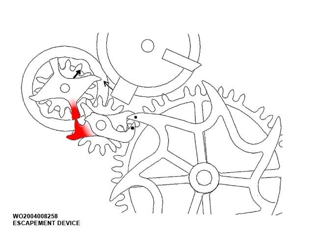
The first locking point (S1 in the diagram) (pinion 20 and the wheel 10 are not engaged)
The pinion 20 and the wheel 10 are not engaged during this movement.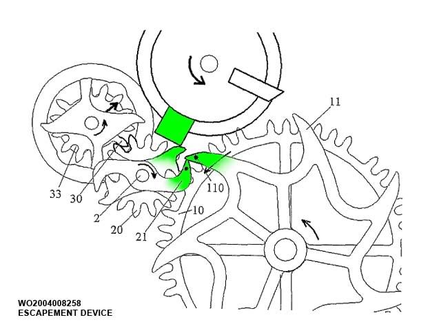
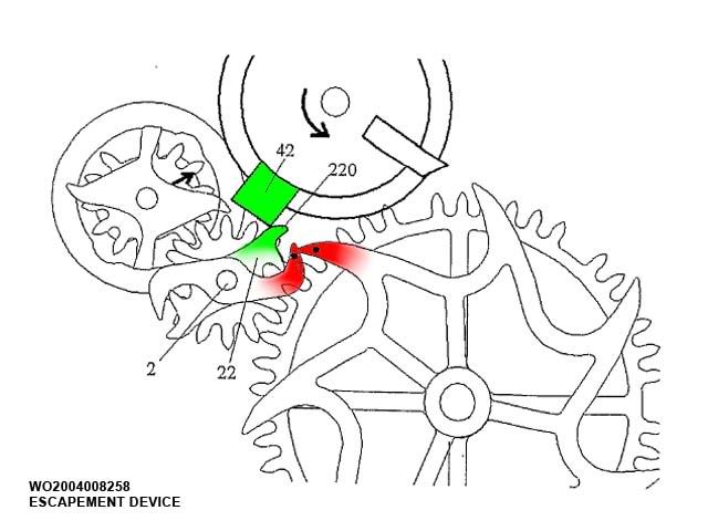
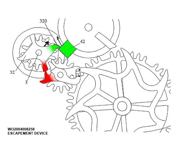
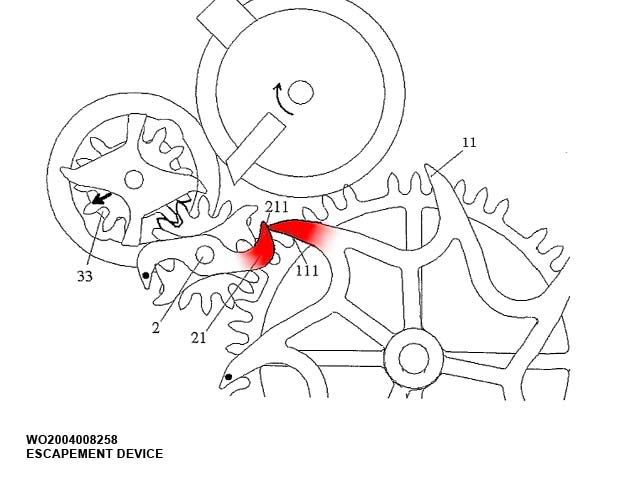
The second locking point (S2 in the diagram)
The impulse wheel is not blocked by the 21. Pinion 20 is blocking the wheel 10 (attached to the impulse wheel-11).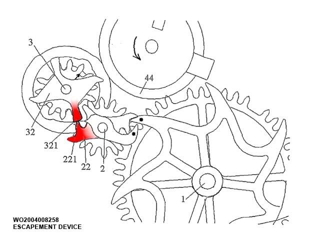
During this movement the pinions 20 and 30 are not engaged.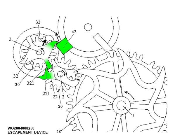
The impulse wheel and the rotor (huh?) in action:
The pinion 30 (attached to the rotor 33) engages with the pinion 20 and drives the wheel 10 (attached to the impulse wheel 11). Note the angle of the rotor (small straight arrow on the pinion) in the next two pictures.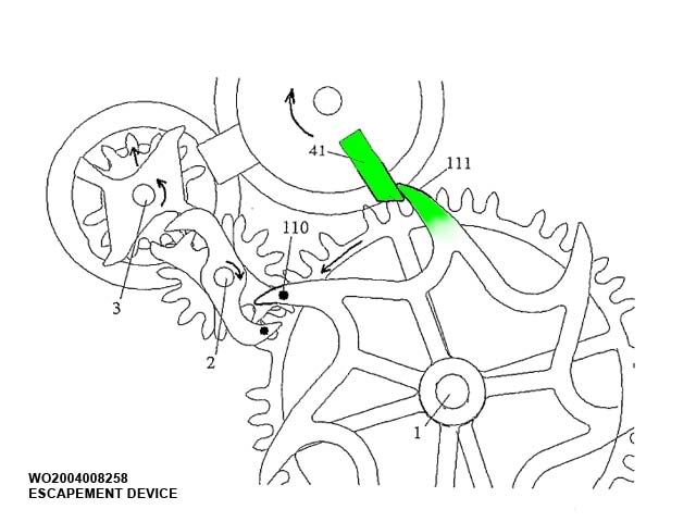
Both the mainspring barrel (through the gear train) and the rotor (through the pinions) drive the wheel 10.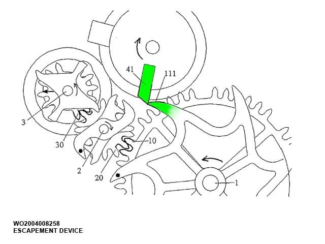
Now the most interesting part:
Of course you won't find these on the wafer...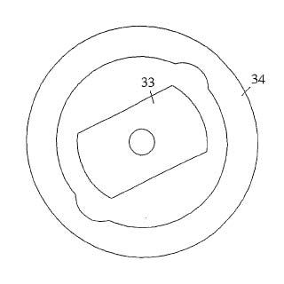
Rotor - Permanent magnet (diametrically magnetized as indicated by the straight arrow on the pinion 30-attached to the rotor 33)
Stator - Ferromagnetic ring with two diametrically opposed recesses. When rotor is set in rotation (leaves the stable point of equilibrium), the presence of these two recesses creates a magnetic couple having an effect on the rotor.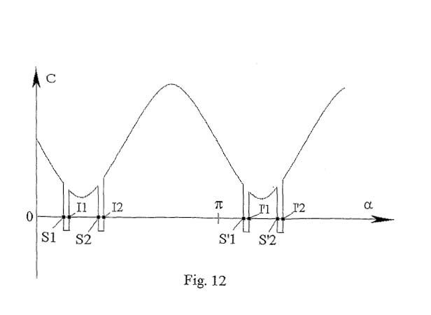
The diagram represents a couple C in relation to the swing angle of the rotor.
This couple C consists of two components: (I) a constant couple coming from the mainspring barrel and (II) a second component varying periodically (sinusoidally) provided by the rotor and transmitted via pinions 30 and 20 to the toothed wheel 10.
The diagram shows that the maximum of energy is transmitted when the impulse wheel 11 hits the 41 (at the moment when the balance is at its maximum speed). In this way, the isochronism is preserved to the maximum extent.
You will find much more information if you click here. All the pictures were created from the patent files (publication number: WO2004008258).
Your corrections, clarifications and comments are welcome.
Mishko
New Patek Escapement

Mishko.....

holy cow
Will this end the Chapter one of the Advanced Research "Triology"

Rotor > clarification
Just wondering... is using magnetization a good idea?